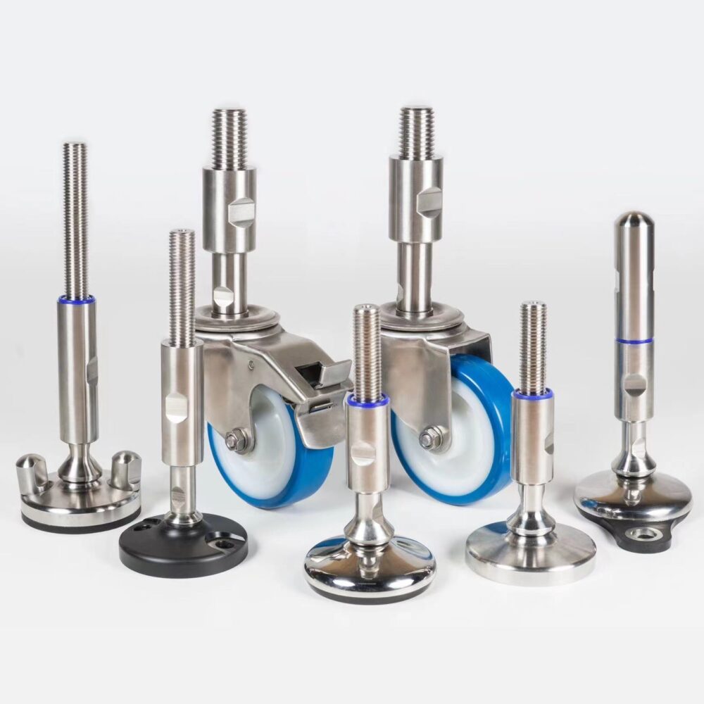
Seismic leveling feet (levelling feet in British English) are leveling feet whose base is anchored to the floor so that a machine stays level in normal operation and cannot slide, walk or tip when ground motion pushes it sideways. They combine an adjustable, often articulating stem with a bolted base plate that carries horizontal shear and uplift. This guide (British spelling: seismic leveling feet; also sold as anti-seismic machine feet) explains when they are needed, how to estimate the forces, and how to keep them hygienic. It builds on the industrial leveling feet selection guide.
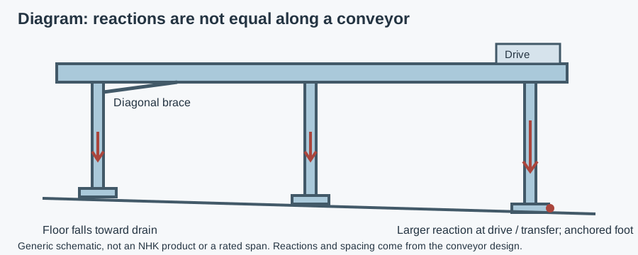
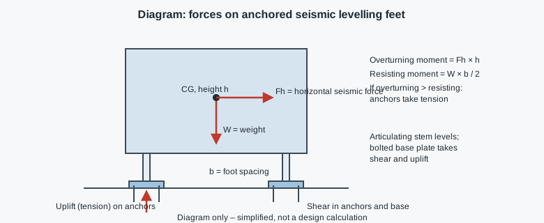 forces on anchored seismic leveling feet. Schematic, not a product test report.
Standard, anchored and seismic feet compared
| Feature | Free-standing leveling foot | Anchoring foot (fixing holes) | Seismic leveling foot |
|---|---|---|---|
| Vertical load | Yes | Yes | Yes |
| Horizontal load | Friction only | Through anchors, modest | Designed for the required shear |
| Uplift / overturning | No | Limited | Designed with anchors for tension |
| Articulation | Often | Often | Usually, with locking after leveling |
| Typical use | Stationary machines in non-seismic areas | Machines that vibrate, walk or must not move | Machines in seismic zones, tall or top-heavy equipment |
| Who decides | Machine builder | Machine builder | Local building code and the plant's structural engineer |
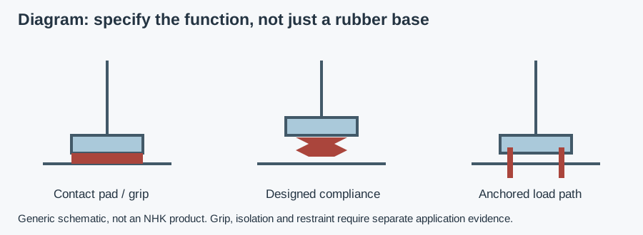
The difference between an anchoring foot and a seismic foot is not the holes but the verified capacity: the foot, its stem connection, the base plate and the anchors must all carry the design forces. For the anchoring basics, see one or two fixing holes.
Send your application data and get a recommendation for anchored feet
When are seismic leveling feet needed?
- The plant is in a region where the building code requires anchorage of equipment – in Europe under EN 1998 (Eurocode 8) and its national annexes, in the US under the building code and ASCE 7.
- The machine is tall or top-heavy relative to its footprint: silos, tanks, tower freezers, racks, tall packaging machines.
- The machine contains hazardous or hot media, or its failure would block escape routes.
- The insurer or customer specification requires anchorage.
In low-seismicity regions, ordinary anchoring feet are often enough for machines that vibrate or walk. The decision on seismic anchorage and the design forces belongs to the plant's structural engineer, not to the foot catalog. For certificate checks, use the EHEDG certification guide.
How seismic feet work
- The stem sets height and levels the machine; an articulating ball joint accommodates floor slope.
- A lock nut or locking mechanism fixes height after leveling so vibration cannot change it.
- The base plate carries the vertical load to the floor and transfers horizontal force to the anchors.
- Anchors (post-installed bolts in concrete) take shear and, when the machine tends to tip, tension.
- The connection between stem and base must carry the same horizontal force – an articulating joint that is strong vertically may be weak in shear or pull-out. Ask for the supplier's horizontal and pull-out values.
Force estimate – simplified method
For a first check before the structural engineer's calculation:
- Horizontal seismic force: Fh = seismic coefficient × W, where the coefficient comes from the building code for the site and the equipment's mounting height.
- Overturning moment: M = Fh × h, with h = height of the center of gravity above the floor.
- Resisting moment: W × b / 2, with b = distance between feet across the direction of motion.
- If M exceeds the resisting moment, the anchors on one side take tension: T ≈ (M − W × b/2) ÷ b, shared between the anchors on that side.
- Shear per foot ≈ Fh ÷ number of anchored feet.
Example (assumptions, for method only): a tank of 2,000 kg (W ≈ 19.6 kN) on four feet, b = 1.0 m, center of gravity h = 1.5 m, assumed seismic coefficient 0.3. Fh = 5.9 kN; M = 8.8 kNm; resisting moment = 9.8 kNm. No net uplift at this coefficient, but shear per foot ≈ 1.5 kN must go through the base and anchors. With a coefficient of 0.4, M = 11.8 kNm and uplift ≈ 2.0 kN on one side. The real coefficient must come from the code and the structural engineer; the example only shows how quickly tall equipment moves into uplift.
Hygienic seismic feet
Anchoring creates hygiene problems: bolt heads, washers and the gap under the base plate are harborage points, places where residues collect and survive cleaning. In wet areas:
- Use stainless steel feet and anchors (AISI 304; 316 near chlorides) to avoid galvanic corrosion between dissimilar metals.
- Prefer designs with enclosed threads and sealed bases, so no exposed thread sits in the splash zone.
- Seal the base to the floor or use a base with an integrated seal; an open gap under a bolted plate collects water.
- Use hygienic bolts or covers over anchor heads where available.
- Keep enough clearance under the machine for cleaning.
NHK lists machine levelling feet; do not assume seismic suitability without documented engineering verification of the selected foot, anchorage and installation. For hygienic foot design in general, see hygienic leveling feet design.
Installation and inspection checklist
- Check concrete thickness, strength and edge distances against the anchor supplier's data.
- Level the machine, then lock the stem before final anchor torque.
- Torque anchors to the anchor supplier's value; record it.
- Seal the base and anchor heads where the zone requires it.
- Re-inspect after commissioning and periodically: anchor torque, lock nuts, cracks in floor around anchors, corrosion, seal condition.
Common mistakes
- Treating fixing holes as seismic capacity without checking stem and joint strength.
- Leveling after anchoring, which preloads the joint.
- Mild-steel anchors under stainless feet in wet areas.
- Anchors too close to slab edges or floor drains.
- Unsealed bases that collect water under the plate.
What to send for a recommendation
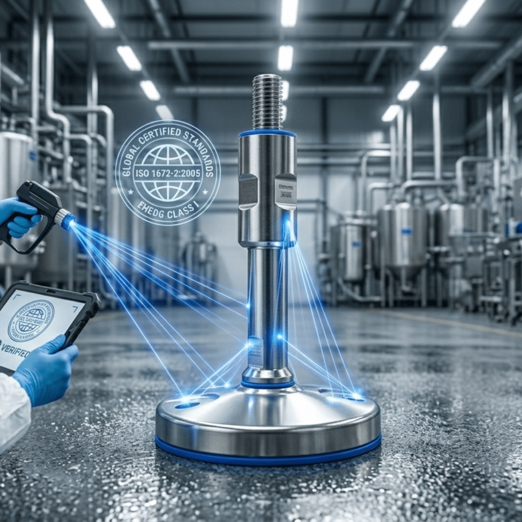
Before asking for certification evidence, use the checking hygiene certificates separately from anchorage data.
- Machine weight, center-of-gravity height, footprint and number of feet
- Design horizontal force or seismic coefficient from the structural engineer
- Floor: concrete, coating, slope, drains
- Zone and cleaning method; material grade
- Thread size, stem length, articulation needed
- Documents: load data, material certificates, hygiene certificates if needed
Send these details to NHK
An NHK technician suggests suitable feet and sends a quote. To compare with mobile options, see casters vs leveling feet.