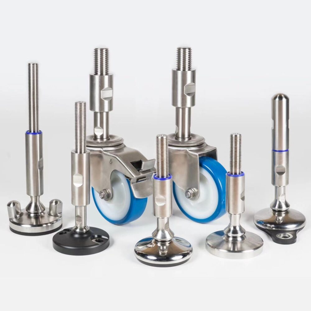
Swivel leveling feet let the base change angle relative to the machine-support stem. They are also called articulated levelling feet in British English. This guide concentrates on angle, loaded geometry and joint cleaning; use the industrial foot sizing and support guide first to establish the machine's support requirements.
What articulation changes—and what it does not
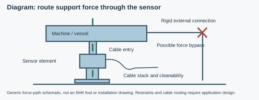
If the support must measure weight, check sensor load introduction and adjustable support geometry separately from base articulation.
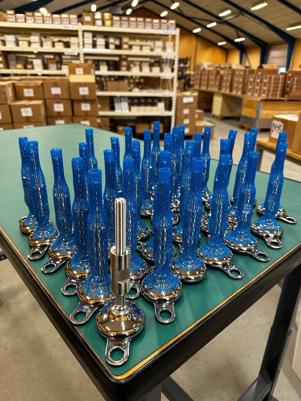
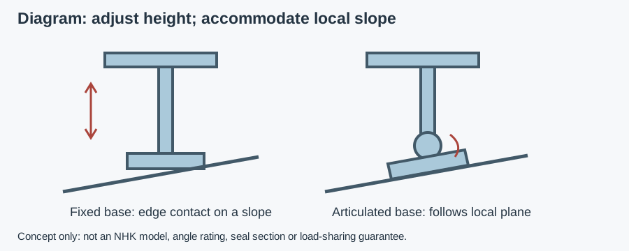
A typical ball-and-socket joint lets the base tilt while the threaded stem sets height. These are separate functions. Height adjustment brings the frame to its required level; base tilt accommodates the angle of the surface beneath that foot. Confirm the actual mechanism because “swivel” can also be used loosely for rotation during adjustment.
A rigid base on a slope may contact mainly at an edge. An articulated base can follow a locally planar slope within its permitted movement. It cannot make a warped tile flat, bridge a recess safely or remove debris under the pad. It also cannot guarantee equal support reactions across a rigid frame. Separate floor preparation from foot selection.
Selection criteria for swivel machine feet
| Requirement | What to specify | What to verify |
|---|---|---|
| Local slope | Surface angle in both directions and stem orientation | Permitted operating angle under the intended load |
| Vertical support load | Maximum reaction at each foot, not only average mass | Rating basis, tilt and extension restrictions |
| Stem geometry | Thread, engagement, extension and frame bracket | Bending, adjustment limits and locking instructions |
| Base contact | Diameter, floor strength, pad and surface condition | Intended contact without edge loading or rocking |
| Fixing | Free-standing or anchored; lateral and uplift cases | Joint/base/anchor compatibility and installation detail |
| Ball-joint hygiene | Cleaning zone, exposure and access | Seal contact and residue traps at the installed angle |
| Materials | Actual metal and elastomer specification | Cleaner compatibility and declarations where applicable |
| Certificate | Exact design and variant when required | Scope, supplied configuration and relevant limitations |
Send the slope, support loads and cleaning conditions for a foot recommendation
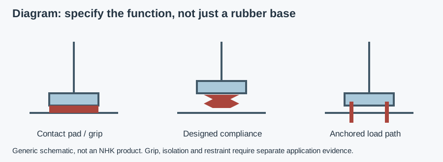
The adjustable versus leveling-foot terminology guide separates height adjustment from joint type. Do not use the label alone to specify a support. A static installation-angle capability is not permission for repeated joint oscillation during production; dynamic articulation requires explicit approval for that duty. On long frames, the guide to legs under conveyors shows where swivel bases sit in the full support path. For elastomer contact bases, check pad deformation and wet-floor grip limits separately from articulation.
Measuring floor slope and interpreting swivel angle
Measure the local support plane at each intended base position, not merely the gradient across the room. A floor draining toward a channel can change direction beside a joint or drain. Record both directions and any bumps within the contact area. Include the stem's installed orientation: a tilted bracket changes the relative angle the joint must accommodate.
For a planar slope measured along its steepest direction, the geometric relation is angle = arctan(rise ÷ horizontal run). Rise and run must use the same units. A percentage gradient is rise/run multiplied by 100; it is not a value in degrees. This geometry calculation establishes an angle, not a product rating or approval.
Ask whether the specified maximum is tilt from the stem axis, total sweep between opposite extremes or another convention. Ask whether it applies under load and with seals fitted. Do not double a stated value or apply an unloaded movement limit to the full rated load. Request an installation drawing showing the permitted condition.
The ball joint still needs room around its neck, socket and seal. At extreme tilt, a shoulder may approach a stop or a cover may interfere. Use the manufacturer's permitted range and any stated allowance for mounting tolerances rather than choosing a foot that only just moves to the measured angle when loose.
Load at tilt, stem extension and fixing
Establish each foot's reaction from machine mass, product, attachments, support layout and center of gravity. Account for startup, braking and other operating forces where relevant. Soft foot means a support does not make its intended contact and tightening or adjustment can distort the frame. The migrated machine-foot stability and vibration guide explains that installation problem.
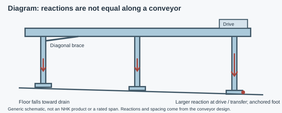
For an initial vertical-load screen, divide total load by the number of feet actually assumed to carry it, then apply the application's justified factor. This is not a substitute for unequal reactions or a frame analysis. Do not assume four installed feet always carry one quarter each; articulation changes the contact angle, not the load-sharing mechanism.
Check the foot rating at the intended angle and stem extension. A centered axial test with a short stem does not automatically cover an extended stem, lateral load or eccentric reaction. Ask for the permitted combination or derating method; no universal angle multiplier or NHK load reduction is claimed here.
For an anchored base, verify that articulation, anchor seating and tightening can coexist in the installed geometry. An anchor must not pull the base away from its intended contact or force the joint beyond its limit. Use the one- versus two-hole anchoring guide for fixing choices, but obtain the actual base and anchor instructions for the selected design.
Ball-joint hygiene at the installed angle
An open socket, neck gap or retaining feature can create harborage points—places where residue survives cleaning. A crevice is a narrow interface cleaning cannot adequately reach. Inspect the joint in the installed position rather than judging only a centered catalogue photograph. Check whether tilting exposes an edge or creates a recess behind a cover.
A seal or sleeve must remain effective throughout the permitted operating angle and extension. Look for damaged lips, displaced covers and exposed thread. Self-draining geometry sheds liquid rather than retaining it, but drainage still depends on orientation. Request the actual cleaning method and any restrictions on jets directed at the joint.
In a splash zone, product or cleaning liquid reaches the support. The foot is normally outside direct product contact, but foreseeable transfer still needs assessment. EC 1935/2004 concerns food-contact materials within its scope, EU 10/2011 plastics and FDA 21 CFR 177.2600 applicable repeated-use rubber articles. A material declaration does not establish joint cleanability or load capacity.
Specify actual alloys and elastomer compounds against the cleaning cycle. AISI 304 and 316L are different corrosion-resistance choices, but neither alone proves suitability for every chloride exposure or cleaner. EPDM, FKM and VMQ identify elastomer families, not interchangeable compound approvals. Ask for concentration, temperature and exposure limits without assuming a family name establishes compatibility.
The sanitary machine-foot design guide provides broader sealed-support context. EN 1672-2 and EN ISO 14159 concern machine hygiene and cleanability; they do not prescribe a universal swivel angle. EHEDG certifies specific designs, and voluntary 3-A Symbol authorization follows Third Party Verification. Check the certificate scope and design-verification guide rather than transferring a certificate between foot variants.
Example: checking a support beside a drain
Assumptions: a stationary packing frame is leveled, its stem is vertical and the local floor plane rises 20 mm over a horizontal run of 1,000 mm in its steepest direction. These are hypothetical geometry inputs, not NHK dimensions or a field case.
The gradient is 20/1,000 × 100 = 2%. The corresponding angle is arctan(0.02), approximately 1.15°. That is the relative geometric tilt required before considering mounting tolerance; it is not the selected foot's permitted angle. Record the actual load reaction and extension, then ask whether the proposed joint and seal support that installed combination.
Next inspect the full base footprint. A local chipped edge or hollow below the pad is not resolved by the 1.15° calculation. Correct the support surface or select an engineered mounting arrangement. Finally recheck all feet for contact and frame alignment: a well-seated base at this location does not establish that neighboring supports carry their intended loads.
Installation and inspection: five acceptance steps
- Prepare the support surface. Remove debris and inspect damage, floor strength and local slope. Reject unintended edge contact or rocking before tightening anchors.
- Follow the adjustment procedure. Isolate the machine and use rated temporary support if required. Do not assume the foot may be adjusted under load or force a seized joint.
- Set height and angle separately. Keep extension within instructions; check frame level, base seating, thread engagement and joint clearance under the intended load.
- Lock and fix as specified. Apply only the stated locking/anchor procedure and torque. Recheck that tightening has not distorted the frame or lifted a base edge.
- Inspect after operation and cleaning. Check level, loose locking parts, seal damage, retained residue and changed contact. Set maintenance intervals from duty and instructions, not an invented schedule.
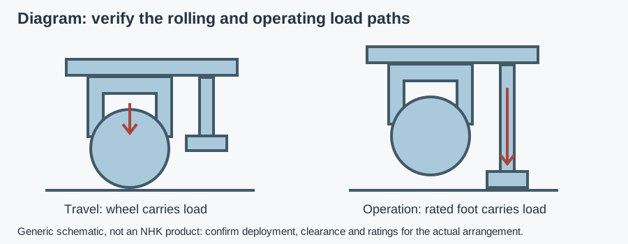
Movement during production, a damaged seal or repeated loss of adjustment calls for investigation, not additional joint travel. Articulation is not automatically vibration isolation. If the machine must move between stations, the casters versus fixed-support comparison addresses that different requirement.
Copyable RFQ and documents to request
Send machine type and loaded mass, support layout and reactions, local floor slope, stem orientation, thread and extension, base diameter constraints, floor condition, anchoring needs, cleaning zone and cycle. Include quantity, known part numbers and delivery country. The buyer's component-specification guides provide wider purchasing context; no dedicated feet-load calculator is available in the current registry.
Copyable request: “Please confirm the permitted loaded articulation angle and rating at our installed stem extension. Provide the joint and seal drawing, adjustment-under-load restrictions, locking and fixing instructions, materials, cleaning limits and maintenance requirements. Identify certificate scope and food-contact declarations where applicable to the exact supplied variant.”
Browse NHK's machine-foot range for variant-specific drawings and selection enquiries as the secondary product path. The checked category does not establish a universal articulation angle, joint seal or load curve. An NHK technician can recommend a suitable component and prepare a quote from the application details; no response time, stock or performance guarantee is claimed.