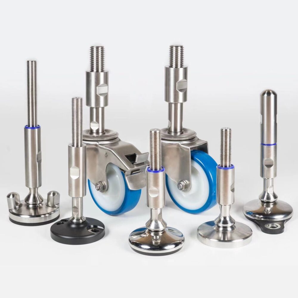
Load cell feet are machine supports with a force sensor in the support path. They can combine height adjustment with weighing, but their measurement depends on the complete installation: load introduction, external connections, cable forces and the indicator. Start with the industrial leveling-foot selection guide for the mechanical support requirements, then specify how the measured force reaches the sensor.
Weighing feet: selection criteria before ordering
Define what you intend to measure: a stationary vessel's contents, changes during filling, or a process trend. Gross load includes the supported equipment and contents; net load is the contents after an appropriate tare, which subtracts the baseline indication. Display resolution is the smallest displayed increment, not proof of measurement accuracy. Specify the acceptable error and repeatability for the actual task separately from the required load capacity.
A foot assembly may integrate the sensor or couple a separate weighing module to an adjustable support. Confirm the architecture before replacing an existing machine foot. Leveling feet (levelling feet in British English) adjust height; ordinary feet do not measure load. A mechanically interchangeable thread does not make a sensor assembly an interchangeable weighing system.
| Selection question | Application data | Evidence to request |
|---|---|---|
| What is weighed? | Empty equipment, maximum contents and required net range | Capacity and measurement basis |
| How is load introduced? | Support positions, center of gravity and reactions | Permitted load direction and mounting drawing |
| What disturbs it? | Agitation, impact, pipe forces and vibration | Overload and restraint provisions |
| What indication is needed? | Error, repeatability, resolution and settling requirement | System specification and acceptance method |
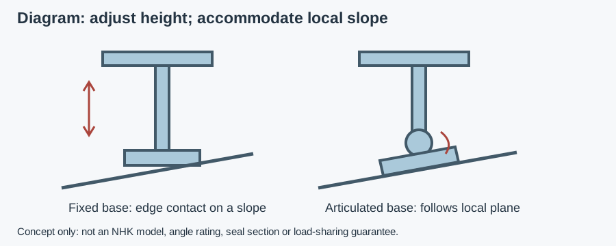
| How is height adjusted? | Thread, extension, floor slope and local seating | Adjustment and articulation limits |
| How is it cleaned? | Zone, chemicals, temperature and cleaning sequence | Complete-assembly cleaning and ingress evidence |
| Where do cables run? | Entry direction, junction location and removal route | Connection, shielding and routing instructions |
| What evidence is required? | Hygiene certificate scope and applicable weighing rules | Exact configuration and supporting documents |
Send weighing and cleaning data for a component recommendation
Load path: do not let pipes or restraints bypass the sensor
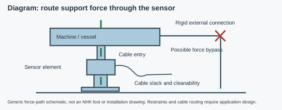
A sensor measures the force transmitted through it, not every kilogram somewhere on the machine. A parallel load path, sometimes called a force shunt, lets part of the load travel through another connection. A rigid pipe, tight hose, guard support, touching frame or engaged transport stop can alter the indication without changing the contents. Examine the complete installation before blaming the electronics.
Place the intended vertical support force through the specified load-introduction interface. Side loads, bending moments and uplift need their own assessment; a vertical capacity is not permission for arbitrary loading. Define restraint against movement while preserving the sensor's intended movement and measuring direction. Do not remove safety restraints just to improve a reading. The weighing-module designer must resolve both requirements.
Flexible connections can reduce transmitted forces, but their installed stiffness, pressure and geometry still matter. Check the empty and full vessel, operating temperature and connected process state. A hose with adequate slack when empty can become tight after movement or thermal expansion. Any proposed flexible connection also needs its own hygienic and pressure/chemical assessment.
Capacity, support reactions and usable measurement range
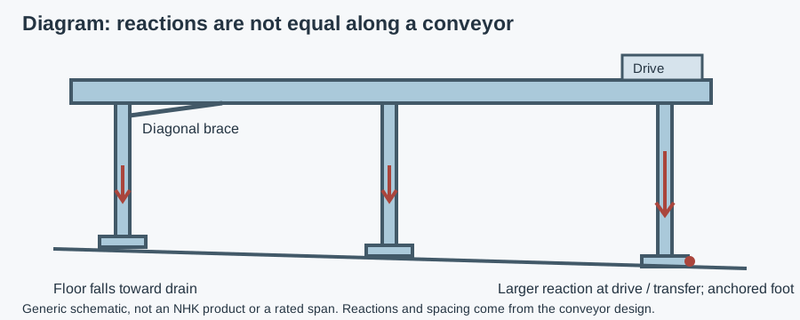
Obtain the maximum reaction at each support for the governing load cases. An average derived from total mass divided by foot count is only a starting estimate when equal sharing is justified. Uneven seating, a shifting center of gravity, frame stiffness and agitation can make individual reactions unequal. Ask the machine designer for normal, startup, maintenance and abnormal cases as applicable, including overload and uplift requirements.
Select both the mechanical foot rating and sensor capacity for their actual installed conditions. Thread extension, articulation, attachments and restraints can impose separate limits. Do not use a universal safety factor or assume a safe overload value; take these from the selected assembly's documentation and design assessment. The swivel-foot guide to loaded angle and seating explains why base articulation does not establish equal support loading.
A larger sensor capacity does not automatically improve usable weighing performance. A small net change on a large equipment tare requires a system error budget covering sensor behavior, indicator, installation forces and operating conditions. Ask how calibration, zero stability, repeatability and temperature effects are specified for the complete system. Do not convert a catalog accuracy class into a guaranteed installed batch error.
Hygienic load cell feet: surfaces and cleaning interfaces
A product-contact zone directly touches the food; a splash zone receives product or cleaning liquid without intended direct contact. Floor-level supports are often outside direct product contact, but assess foreseeable transfer and the surrounding layout. A stainless enclosure alone does not establish cleanability of its cable gland, adjustment mechanism, mounting seat or underside.
A crevice is a narrow gap that retains liquid or residue beyond effective cleaning. A harborage point is a location where residue survives the procedure. Inspect where the stem meets the sensor body, where covers join, where the base meets the floor and where cables enter. Self-draining surfaces release liquid rather than leaving a pool; check them at the actual height and angle, not only on a drawing.
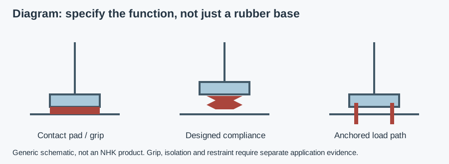
Confirm the materials of body, stem, base, seals and cable jacket against the chemicals and use conditions. A generic elastomer name is not compound-specific compatibility evidence. If a rubber pad is present, the rubber-foot guide to grip versus isolation helps separate floor contact from vibration behavior. An isolation element can change movement and settling; it cannot be assumed suitable for a weighing requirement.
Ask how the foot is inspected and cleaned without disturbing the load-introduction detail. Document any permitted dismantling, reassembly and recalibration. Forcing a tool beneath a loaded support or loosening it during cleaning can create a mechanical hazard and invalidate the setup; use the approved isolation and support procedure.
Cable routing, glands and the junction box
Treat cable routing as part of the weighing installation and hygiene assessment. Follow supplier limits for bend radius, connection, shielding and separation from interference sources. Do not prescribe a universal routing distance or grounding scheme. The sensor, indicator and wiring instructions must agree; changes to cable length or terminations need supplier approval where relevant.
Provide enough controlled movement that the cable does not pull on the sensor as the machine settles or is adjusted. Too much loose cable can create floor contact, loops that retain residue or a snagging hazard. Locate supports so cable slack is deliberate and inspectable. Avoid a tight tie that applies force to the sensor or traps liquid against its housing.
Place the junction box and connector where they can be inspected and serviced safely. Check cable entries, unused openings, sealing surfaces and the path of cleaning runoff. An enclosure ingress rating applies to a defined configuration; an inappropriate gland or connector can change that configuration. Removing a cover for service also requires an approved method for restoring its sealing condition.
“EHEDG compliant load cell”: what evidence does that mean?
The phrase EHEDG compliant load cell does not identify a certificate or prove that the installed foot is certified. EHEDG certification is voluntary and applies to specific equipment designs within the certificate's scope. Ask for the exact manufacturer, design designation, certificate and installation restrictions. A certificate for an ordinary leveling foot cannot be assumed to cover a weighing sensor added to it. Use the official EHEDG equipment register to check the supplied designation and scope.
Hygienic design guidance and ingress testing answer different questions. IP67 is an immersion test, not a washdown rating or chemical-resistance statement. For pressure cleaning, request the applicable standard, test conditions and complete configuration, along with cleaning instructions. The open and closed system cleaning comparison distinguishes external cleaning access from cleaning-in-place of product circuits; a sealed sensor housing is not evidence of a CIP system.
Calibration establishes the relationship between applied reference loads and indication under the specified procedure. It does not establish hygienic design. Where weighing results have a regulated commercial or control purpose, obtain the applicable jurisdictional requirements for the complete instrument. Do not infer legal-for-trade suitability from the sensor label alone.
Use the certificate search and weighing-assembly scope checklist to compare the offered sensor or support configuration with the register evidence.
Example: investigate a filling vessel before choosing the feet
Example — hypothetical assumptions, not NHK field observations. Assume a stationary mixing vessel on adjustable supports, connected to feed and discharge lines, with a need to monitor net filling changes after external foam cleaning. The aim is to define the selection and acceptance method, not claim a capacity or accuracy.
- Obtain the empty equipment and maximum-content loads, support positions and individual reaction envelope. Ask how agitator operation, off-center contents and maintenance alter the cases.
- Mark every external connection on the drawing. Check pipe and hose force paths, safety restraints and cable supports through the expected height and temperature range.
- Specify the required net weighing error and repeatability independently of display increments. Agree whether readings are taken stationary, during filling or with agitation stopped.
- Review the sensor body, adjustment seal, cable entry and junction-box cleaning interfaces. Request compatibility and any exact-design certificate rather than assuming a stainless finish is sufficient.
- Agree tests using suitable reference loads in representative positions and process states. Record the approved baseline, repeatability and post-cleaning checks; do not substitute an empty zero check for loaded verification.
If a connected pipe imposes a variable force outside the accepted error budget, a different connection or weighing architecture may be needed. A compact integrated foot is not the right choice merely because it fits the existing mounting thread.
Installation and post-cleaning acceptance checks
Use trained personnel, safe isolation and the manufacturer's mounting procedure. Support the machine safely during replacement; do not adjust a loaded measuring assembly unless its instructions permit it.
- Confirm load-introduction orientation, attachment and restraint clearances against the drawing. Check that shipping or overload stops are in the intended operating condition.
- Inspect floor seating and all support contacts, then check for unintended touches at guards, pipework or connected equipment.
- Set cable routing and inspect glands, connectors and box closures before calibration. Record installed adjustment and connection states.
- Verify zero, span and repeatability with an agreed reference-load procedure. Check representative load positions where uneven sharing matters.
- Repeat relevant checks after height adjustment, connection changes, sensor replacement or maintenance. Investigate post-cleaning shifts before simply re-zeroing.
| Symptom | Possible cause | How to check | Corrective direction |
|---|---|---|---|
| Reading changes after a pipe reconnection | Connection force bypass | Compare approved process/connection states | Correct connection design and reverify |
| Unstable indication during motion | Vibration, cable force or process loads | Compare stationary and operating conditions safely | Resolve mechanical/electrical cause before filtering |
| Zero shifts after cleaning | Retained liquid, temperature effects or changed contacts | Inspect interfaces and allow the defined stabilization condition | Address cause; check loaded response as well as zero |
| Different reading with load position | Unequal introduction or support interference | Use agreed reference-load positions | Correct mounting and validate system adjustment |
| Visible seal or cable damage | Incompatible exposure or mechanical strain | Inspect against documented cleaning/routing conditions | Replace approved parts and correct the exposure |
For a conveying machine, the conveyor frame and component selection guide provides the surrounding assembly context; do not let a connected transfer or frame support become an unintended weighing-force path.
RFQ: send the weighing task and the complete support layout
Copy and complete: “Machine/vessel and drawing: __. Empty and maximum gross loads, support reactions and movement: __. Required net range, acceptable error, repeatability and reading conditions: __. Thread, height adjustment, floor and restraints: __. Pipes, hoses, cable routes, junction box and indicator: __. Zone and cleaning chemicals, concentrations, temperature and method: __. Required certificate scope, materials and applicable weighing documentation: __. Part numbers if known, quantity and delivery country: __.”
The buyer's support-specification guides provide the broader document-request path for this weighing task.
For a broader discussion of support requirements in precision applications, see machine-support choices for precision equipment. NHK's stainless adjustable machine-support category is the starting point for support enquiries, not proof of a load-cell-foot range. Ask NHK to confirm available weighing-foot arrangements and supporting documents before specifying a product. An NHK technician can assess the component request and propose available options and a quotation; the weighing-system designer still needs to validate the installed result.