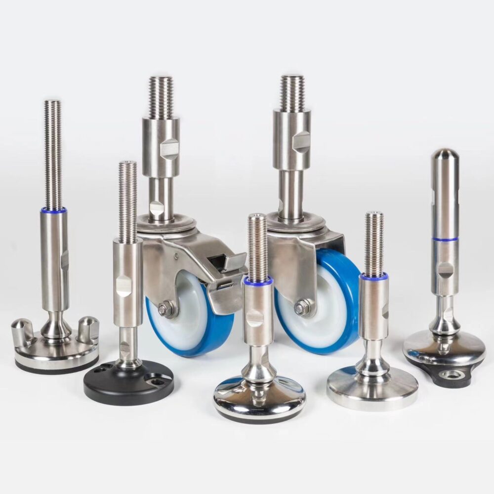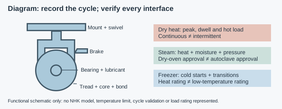
Levelling castors are selected for two jobs: moving a machine and supporting it in its operating position. The US term is leveling casters. This guide focuses on castors with levelling feet; the industrial castor selection and load guide provides the wider rolling-assembly context. Confirm the actual mechanism before specifying a combined unit.
Integrated foot or height-adjustable castor: check the drawing
Suppliers do not always use “levelling” to describe the same arrangement. One design has a separate pad that lowers beside or within the wheel assembly. Another changes the height of a castor through a threaded mounting spindle while load remains on the wheel. A drawing showing only a threaded stem does not establish a foot-supported operating state.
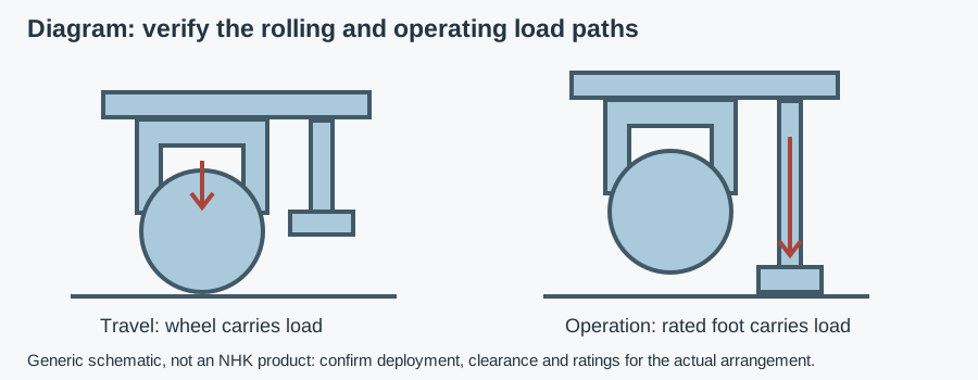
For an integrated design, trace the load path with the pad retracted and deployed. Determine whether deployment is intended to lift the wheel clear or create another specified support arrangement. Confirm the mechanism, travel and permitted load; do not treat incidental pad contact as proof that the wheel has been unloaded correctly.
Selection table: two states, separate requirements
| Criterion | Rolling state | Foot-supported operating state |
|---|---|---|
| Capacity | Rated load at stated speed, floor and duty | Pad, adjuster and mounting capacity at permitted extension |
| Geometry | Wheel diameter, swivel clearance and released pad height | Adjustment range, pad seating and wheel clearance |
| Floor | Joints, thresholds, slopes and damage | Local slope, floor strength and intended contact |
| Forces | Pushes, towing if permitted, shocks and turns | Process reactions, lateral forces and stability |
| Access | Safe movement and control of equipment | Safe adjustment without reaching beneath unsupported loads |
| Cleaning | Wheel, axle, swivel and released mechanism | Pad edge, adjustment interface and deployed recesses |
| Fixing | Plate or stem attachment to frame | Same attachment plus operating load path; anchoring if required |
| Evidence | Rolling rating and movement restrictions | Static rating, deployment/locking instructions and cleaning limits |
Send the rolling and operating requirements for a component recommendation
The castors versus fixed-foot comparison addresses which support approach to choose. Here the question is whether a specific combined assembly meets both states. Do not assume an integrated design is suitable for frequent transport, powered towing or high speeds; obtain the movement conditions for the selected variant.
When castors with levelling feet make sense
Consider the arrangement when equipment is repositioned between campaigns or layouts but must run at a defined height and level. It can reduce the need for a separate wheel-and-foot mounting arrangement, but it adds an adjustment mechanism and another set of interfaces to clean. Check whether the operator can reach and deploy every unit safely.
Separate castors and feet may be preferable where larger wheels, more adjustment, accessible anchoring or simpler hygienic supports are required. Permanently fixed machines may not need wheels at all. Frequent movement and repeated adjustment can make an integrated mechanism inconvenient; selection depends on travel frequency, floor, operating loads and access rather than a general preference for combined parts.
A support pad is not automatically an anchor or vibration isolator. Compliance means the support deflects under force; a rubber pad can remain compliant after the wheel is unloaded. If operating alignment or restraint is critical, assess the complete frame, pad and fixing arrangement rather than equating “stands on feet” with absolute rigidity.
Rolling load and static foot load: calculate separately
Start with machine, payload, attachments and the most demanding operating condition. Establish support reactions from their positions and the centre of gravity, the point through which the weight acts. A simple average can hide a heavily loaded corner. Uneven floors, frame stiffness and adjustment also change which supports carry load.
For an initial screen, load per support is total load divided by the number actually assumed to carry it, with a justified application factor where appropriate. Confirm that assumption with the designer and supplier; do not prescribe a universal factor or assume all fitted units share equally. Check rolling and deployed-foot ratings against their own conditions.
The machine-foot sizing and anchoring guide covers stationary support checks. The migrated support contact, soft foot and vibration guide explains soft foot: a support does not make its intended contact and adjustment or tightening can distort the frame. Adding more units does not itself solve unequal reactions.
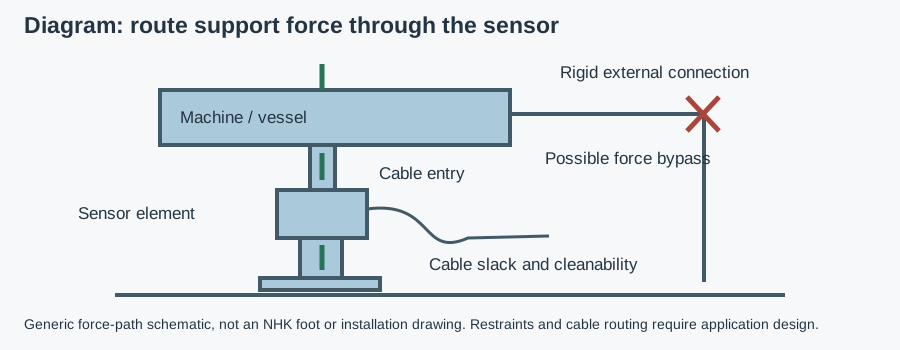
Check whether the static rating covers pad extension, lateral forces and the intended adjustment-under-load method. The wheel may have a different capacity from the pad or screw. Neither establishes the frame bracket's rating. Service lifting, caster replacement or work beneath equipment requires an approved support method; an integrated adjuster is not automatically a maintenance jack.
Pad travel, floor slope and wheel clearance
Compare pad travel with caster mounting height, floor variation and required machine adjustment. Check the retracted pad through the travel route, including drains and thresholds; dragging can damage the pad or disturb the machine. Check the deployed state against the manufacturer's specified clearance and contact criteria, not an invented clearance dimension.
A flat pad cannot automatically follow a local slope or bridge a damaged tile. Confirm whether articulation is provided and the permitted geometry under load. Do not add loose shims or improvised extensions to compensate for insufficient travel without an engineered detail, particularly where they create inaccessible residue interfaces.
After deployment, verify frame level, all intended pad contacts and wheel unloading as specified. A machine can appear level while one foot carries little load. Conversely, one pad can bear excessive reaction. Locking and adjustment should maintain the intended state during operation; repeated loss of level calls for investigation rather than forcing the adjuster further.
Hygiene of the integrated mechanism
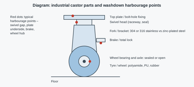
Inspect pad edges, adjustment screws, handwheels or ratchets, covers, swivel bearings and mounting joints. A harbourage point is a place where residue survives cleaning; a narrow inaccessible interface is a crevice. The mechanism may present different exposed surfaces when released and deployed, so assess both positions with safe restraint maintained.
In a splash zone, product or cleaning spray reaches the support. Specify access, drainage and cleaning chemistry for the complete arrangement. Self-draining surfaces shed liquid rather than retain it; covers and pad recesses still need assessment in their actual orientation. An enclosed-looking adjuster can hide residue if the cleaning method cannot reach or remove it.
Use the stainless castor assembly and washdown guide to separate fork, wheel, bearing and seal requirements. Confirm actual stainless grades, wheel/pad compounds and chemical limits. Colour is not evidence of composition or food-contact status. A cleaning-compatible wheel cannot compensate for an incompatible pad or a contaminated adjustment cavity.
EC 1935/2004 concerns materials within its food-contact scope; EU 10/2011 applies to plastics and FDA 21 CFR 177.2600 to applicable repeated-use rubber articles. Material evidence does not prove mechanical capacity or cleanability. EN 1672-2 and EN ISO 14159 concern hygiene requirements, not a universal integrated-foot approval.
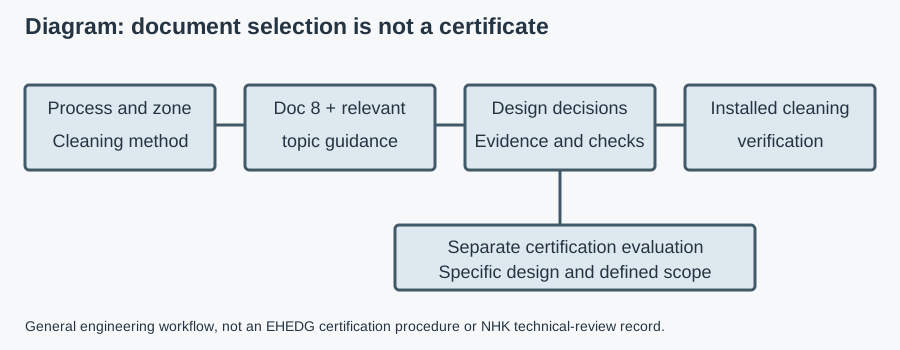
EHEDG certifies specific designs, and voluntary 3-A Symbol authorisation follows Third Party Verification. Use the hygienic-design certificate scope guide when certification is required. No certificate for a separate NHK foot or bearing is transferred to a combined castor arrangement. Likewise, an ingress rating is not a hygiene certificate or proof of load-transfer performance.
Brakes and floor locks are not the same mechanism
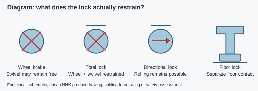
A wheel brake restrains rotation, and a total lock also restrains swivel movement. Neither creates a levelling support path. A separate floor lock commonly resists movement through pad contact while wheels still carry the load. The parking brake and floor-lock comparison separates these functions from a rated deployed foot.
Do not use braking or frictional floor contact as proof of anchoring or safe restraint on a slope. For repositioning, plan how the machine is controlled when feet are released and load returns to the wheels. Follow instructions on brakes and support sequencing; avoid uncontrolled movement while adjusting one corner.
Example: a movable packing module
Assumptions: a packing module moves between two positions during planned changeovers and operates stationary on a wet-cleaned floor. It needs a defined working height. No load, travel dimension or product rating is assumed; this is a hypothetical selection exercise, not an NHK case.
The engineer establishes rolling reactions and operating pad reactions separately. A candidate is retained only if its adjustment travel, frame attachment and documented ratings cover both states. The cleaning team checks the released and deployed mechanism, including the pad recess and adjuster. If access or pad contact is inadequate, separate wheels and hygienic feet are considered instead.
Acceptance records retracted travel clearance, deployed contact, wheel unloading, frame level and adjustment locking against the selected instructions. Releasing the feet is also checked with a controlled movement procedure. The exercise produces a support-state specification, not a recommendation from thread size or an assumed combined-unit rating.
Deployment checks and copyable RFQ
- Confirm the actual assembly. Identify integrated foot versus height-adjustable spindle, rolling/static ratings and adjustment limits.
- Prepare and restrain safely. Isolate the machine and follow the manufacturer's support and movement-control sequence; do not work under unsupported equipment.
- Deploy within instructions. Check all pads, frame level, adjustment range, locking and wheel clearance without forcing seized parts.
- Inspect after operation and cleaning. Look for drift, looseness, pad damage, retained residue and incomplete retraction. Restore the approved state before use.
- Document the return to travel. Verify pad clearance, rolling control and route before movement; set maintenance intervals from duty and supplier instructions.
Send machine and payload, support layout, travel frequency, floor condition, working-height range, mounting drawing, operating forces and cleaning cycle. Include quantity, known part numbers and delivery country. The buyer's component-specification guides provide purchasing context; no dedicated levelling-castor selector exists on this site.
Copyable RFQ: “Confirm whether the proposed assembly has a separate deployable support foot. State rolling and foot-supported ratings, adjustment restrictions, retracted/deployed clearances and mounting requirements. Provide materials, cleaning access and limits, maintenance instructions and certificate scope for the supplied configuration.”
NHK's castor category for levelling arrangement and spindle enquiries lists named levelling-castor entries and spindle variants. Those names do not establish an integrated support foot or its capacity. Send the drawing requirements so an NHK technician can confirm availability, recommend the appropriate arrangement and prepare a quote; no stock, response time or performance guarantee is claimed.