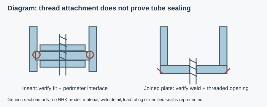
Threaded tube inserts create an attachment point inside a tube end; they should be selected as part of the frame connection, not as a cosmetic cap. The hygienic fastener and fitting selection guide establishes the surrounding joint requirements. Here the additional questions are internal fit, retention and preventing an inaccessible tube cavity from receiving cleaning water or product.
Tube end inserts: identify the retention and load path
An insert may contain a molded thread, a captured metal nut or a machined metal socket. Its body may grip the tube wall, expand against it or be joined permanently. An unthreaded end plug simply closes or protects an edge; it is not equivalent to a rated threaded support fitting.
Determine where the force goes. In some arrangements a flange seats against the tube end and transmits compression there; others depend on internal grip or a welded connection. Pull-out, side loads and torque can use different paths from vertical compression. Obtain the actual section drawing rather than assuming any insert with a suitable thread carries a machine foot.
Plastic, metal and welded inserts compared
| Arrangement | Why consider it | Mechanical check | Closure and cleaning check |
|---|---|---|---|
| Ribbed plastic insert with threaded element | Removable or push-in attachment where documented duty permits | Fit range, nut capture, creep and retention | Perimeter gap, compound compatibility and thread opening |
| Metal interference-fit socket | Rigid threaded attachment without a weld | Tube tolerance, installation force, rotation and pull-out resistance | Fit alone is not a verified liquid seal |
| Expansion-type insert | Grip created by a specified tightening mechanism | Expansion force, thin-wall distortion and torque limits | Added joints, recesses and access for cleaning |
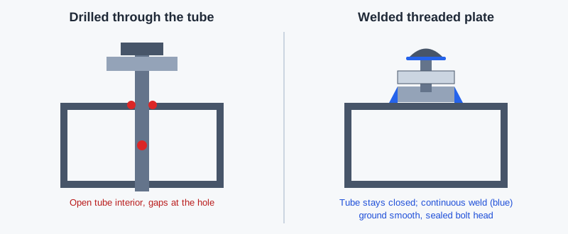
| Weld-in threaded socket or end plate | Permanent frame attachment | Tube wall, weld load path and finished thread | Continuous closure detail, finish and threaded connection |
| Plain end plug | Edge protection or non-load-bearing closure | Do not assign thread/support duty it does not have | Decorative closure is not proof of hygienic sealing |
Send the tube and application details for a component recommendation
These are general construction options, not an NHK range claim. For an alternative permanent threaded attachment, the welded plate and frame-fixing guide addresses the weld interface. Choose by the installed load and cleaning requirement, not merely by whether the insert body is metal or plastic.
Threaded inserts for square tubes: measure the inside
Specify outside section size and wall thickness, then verify actual internal dimensions. For a simple nominal round tube, internal diameter is outside diameter minus twice the wall thickness. That arithmetic is a starting point, not a fit tolerance: ovality, coatings, burrs and the internal weld seam can change usable space.
For square tubes, record both internal flat-to-flat dimensions and the corner profile. A square insert with sharp corners may interfere with a tube's internal radii even if its width appears correct. A seam can obstruct a rib, shoulder or seating surface. Do not grind the insert or remove the tube seam unless the design and manufacturing instructions permit it.
Use representative production samples, not one unusually loose tube offcut. Check end-cut squareness, deburring and insertion depth. Record whether the flange seats fully without splitting the body, distorting the tube or leaving a recess. Interference and rib deformation should follow the supplier's method; no universal press-fit allowance is prescribed here.
Thread engagement, rotation and supported load
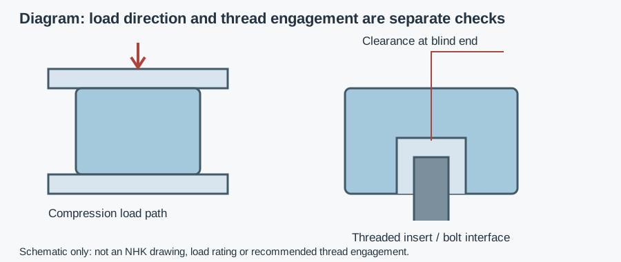
Specify thread diameter, pitch, usable engagement and whether the hole is blind or open. A leveling-foot stem can bottom before its shoulder seats, or project into a cavity where it interferes with another part. Confirm projection through the complete bracket or insert stack; thread size alone is not a capacity specification.
Separate compression from tension, pull-out and side load. A flange bearing against the tube end may carry compression without demonstrating resistance to a stem pulling the insert out. Adjustment torque may rotate an otherwise seated insert. A foot's published rating does not establish the insert, tube wall or complete frame connection has that rating.
For sustained loading of plastic, request the exact compound's allowable duty, temperature and relevant creep data. Creep is time-dependent deformation under sustained load; it is not resolved by a short installation check. For metal sockets, check tube distortion and retention rather than assuming a rigid material makes every press fit adequate.
The spacer and threaded-stack mounting guide helps with adjacent engagement and joint geometry. Keep adjustment within the supplied instructions and do not invent torque, engagement length or pull-out values. If the machine must be lifted by the attached fitting, that is a separate lifting load case requiring an approved arrangement.
Hygienic tube closure is more than a snug plug
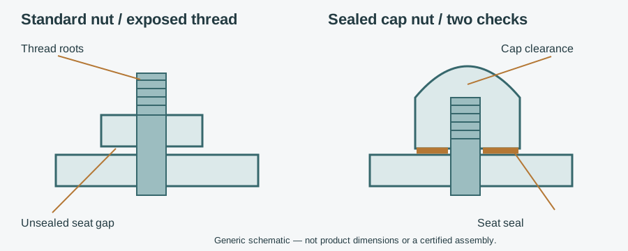
An inaccessible hollow frame becomes a problem if water or product enters but cannot be removed by the intended cleaning process. Check every entry route: insert perimeter, female thread, projecting stem, weld discontinuities and other frame penetrations. Closing one end does not seal a tube already opened by a bolt elsewhere.
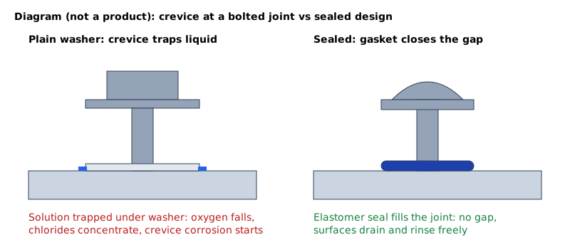
An open perimeter or recessed flange can form a harborage point, where residue survives cleaning. A crevice is a narrow interface that cleaning cannot adequately reach. Assess the assembly with its foot or fitting installed; a neat tube-end photograph does not show the thread path or the hidden flange seat.
Where the hygiene design requires a sealed cavity, specify how closure is achieved and verified under the cleaning exposure. Do not turn a loose push-in cap into a “sealed design” by adding an unspecified bead of sealant. The seal material, surface preparation, geometry, replacement and compatibility need a controlled detail. Removable arrangements need an inspection and reassembly method that restores the intended closure.
For welded closure, assess the complete perimeter and threaded opening, not the word “welded.” A tack weld retains a component locally but does not close the rest of the interface. External surfaces should remain accessible and self-draining—able to shed liquid rather than hold it. Welding, finishing and inspection must match the design, without assuming grinding alone proves a sound joint.
Materials, zones and evidence to request
Specify actual metal grades, polymer compounds and any seals. Stainless construction does not establish resistance to every detergent or chloride exposure. Use the migrated 304 versus 316L material comparison for alloy context, then confirm the supplied insert's material and the tube/insert combination.
Match polymers and seals to cleaning concentration, temperature, contact time and mechanical duty. A compound suitable for one exposure may not suit a hot repeated cycle under load. Plastic color is not evidence of composition or food-contact status. Do not infer stainless thread material from the appearance of a plastic-bodied insert.
In a splash zone, product or cleaning spray reaches the joint; non-product-contact mounting can still create a contamination route. EC 1935/2004 applies to materials within its food-contact scope, EU 10/2011 to plastics and FDA 21 CFR 177.2600 to applicable repeated-use rubber articles. Request evidence for the intended use, not a generic “food grade” label.
EN 1672-2 and EN ISO 14159 concern machine hygiene and cleanability; they do not supply insert retention ratings. EHEDG certifies specific designs, and voluntary 3-A Symbol authorization follows Third Party Verification. Use the design-certificate scope guide when certification is claimed. No certificate for another bolt, foot or bearing is transferred to a tube insert.
Example: a wet-cleaned square-tube frame
Assumptions: an OEM needs an adjustable support threaded into a square-tube frame. Cleaning spray reaches the tube end, and the internal cavity is not intended to be cleaned. No insert dimensions, loads or seal tests are assumed; this is a hypothetical selection exercise, not an NHK case.
The engineer records internal width, corners and seam, then traces compression, adjustment torque and any pull-out forces. A ribbed insert remains a mechanical candidate only if its documented fit and duty match. It is not accepted as hygienic cavity closure simply because it sits flush. A welded socket or an engineered removable sealed interface is evaluated for the full perimeter and the stem-thread path.
The chosen connection is checked on representative tubing with the installed support. Acceptance includes seating, retention and the specified closure verification after assembly and cleaning exposure. If that evidence is unavailable, the frame detail is revised rather than treating a decorative end plug as proof of a sealed hollow section.
Installation and inspection: five checkpoints
- Confirm the drawing and samples. Check section, wall, seam, corners, end cut and fitting code against the approved fit range.
- Prepare without improvising. Deburr and clean as instructed. Do not force an insert, change ribs or add sealant outside the approved detail.
- Install by the specified method. Control seating, depth, expansion or welding; inspect tube distortion and thread condition.
- Check the assembled load and closure paths. Verify engagement and non-bottoming, resistance to rotation and the stated retention/closure acceptance criteria. Avoid hazardous improvised pull tests.
- Inspect in service. Look for insert movement, cracking, retained residue, damaged seals, corrosion and changed adjustment. Repair or replace to restore the approved connection, not merely its appearance.
Copyable RFQ and next enquiry
Send the tube drawing and tolerances, actual internal measurements, wall/seam/corner details, thread and projection, load directions and duty, retention preference, cleaning zone/cycle and required closure. Include known part codes, quantity and delivery country. The buyer's component-specification guides provide the wider document checklist; no dedicated tube-insert selector exists on this site.
Copyable request: “Please confirm insert availability and fit for the attached tube, including seam and corners. State compression, pull-out and torque limits for the proposed installation. Provide thread engagement, seating depth, materials, cleaning compatibility and the complete cavity-closure detail. Identify inspection criteria and any claimed design certificate for the supplied variant.”
NHK's Conveyor components category is the secondary browsing path. Its square and round tube-insert listing names are browsing references, not approved material, fit, load or sealing specifications. Send the specification so an NHK technician can confirm availability, suggest an appropriate connection and prepare a quote; no response time, stock or performance guarantee is asserted.