Rubber buffers are selected by the load they must manage and the environment around their mounting, not simply by diameter or a matching thread. This guide covers anti-vibration mounts and rubber bumpers with threaded insert in that application context. Start with the hygienic fastener and fitting guide for the surrounding joint; a rubber element introduces movement and different limits from a rigid bolted connection.
Buffer, bumper or anti-vibration mount: define the duty
An impact stop cushions a moving part over a finite stroke. A mount carries a sustained load while allowing controlled movement. An isolator aims to reduce vibration transmitted between machine and support. The same external shape does not establish all three functions, and a soft bumper can be a poor choice for precision alignment.
| Application question | What to specify | Evidence before selection |
|---|---|---|
| Door or guard contacts a stop | Moving mass, approach speed, permitted stopping stroke and repetition | Energy/force-deflection limits and attachment strength |
| Part rests on a rubber support | Compression load, distribution and permitted deflection | Load-deflection curve and long-term behavior under stated conditions |
| Machine transmits vibration | Supported mass, excitation range and allowed movement | Dynamic stiffness, damping and isolation assessment |
| Joint carries side load or uplift | Shear, tension and combined loading | Approval for that load direction and any restraint needed |
| Mount is wet-cleaned | Chemicals, concentrations, temperature and contact time | Exact compound, bond and metal compatibility |
| Product or foreseeable transfer contacts rubber | Intended food and contact conditions | Applicable finished-article food-contact evidence |
Send the buffer duty and cleaning details for a recommendation
Do not use an ordinary buffer as a safety-rated restraint or an unsupported suspension. If failure could allow a machine, guard or attachment to fall or move dangerously, the machine designer must assess retention and the consequence of bond failure. A stainless insert does not make the bonded assembly fail-safe.
Elastomers: choose a compound, not a family name
NBR, EPDM, FKM and VMQ identify elastomer families. Their formulations, fillers, curing and hardness can change mechanical and chemical behavior. Select using the supplied compound's data for product residues and the complete cleaning cycle. Neither color nor a familiar family name establishes food-contact status, temperature limits or compatibility with every sanitizer.
For sealing rather than load-bearing duty, follow the food-equipment gasket and O-ring selection checks; do not transfer a seal recommendation to a buffer without its mechanical evidence.
Ask separately about rubber, rubber-to-metal bonding and exposed metal. Swelling, hardening, cracking or bond damage can change support behavior before the machine visibly moves. A formulation suited to a seal is not automatically suitable for a load-bearing mount; the required deformation and repeated loading are different.
Request the alloy of exposed inserts and washers; use the 304 and 316L material comparison for corrosion context without assuming the supplier uses either grade. Metal compatibility cannot substitute for rubber or bond compatibility.
Record detergent and disinfectant names, concentrations, temperatures at the buffer, duration, frequency and drying. Include oils and fats from production rather than assessing rinse water alone. Changeover cleaning can be more severe than normal production exposure. Recheck compatibility when the plant changes its chemistry instead of keeping the original buffer specification indefinitely.
The food-contact material and documentation guide explains why a compliance statement must identify the article and intended conditions. A supplier's “food grade” wording is not a substitute for the required evidence or a load-deflection curve.
Sizing: load direction, deflection and dynamic behavior
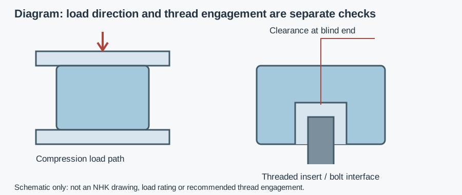
Specify whether the rubber works in compression, shear, tension or combined loading. Compression squeezes it; shear displaces attached faces sideways. Tension can challenge a bonded connection differently from compression. Do not transfer a compression rating to another direction without approval.
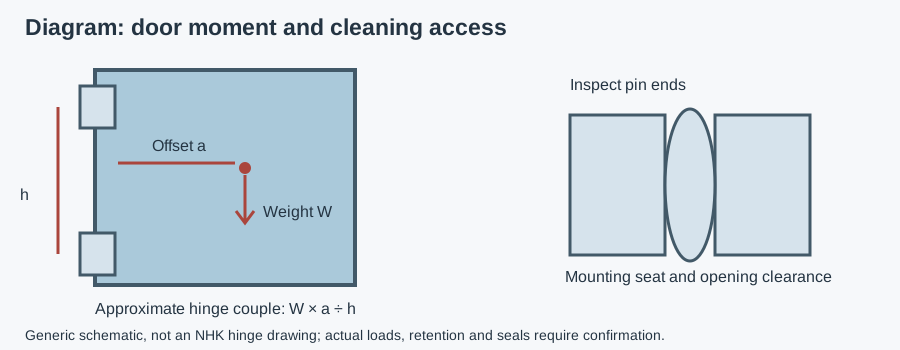
Establish how the supported mass and its center of gravity distribute load among mounts. Machine geometry, piping reactions and operating forces can make loading unequal. Count the mounts that carry the relevant load and review the load cases with the designer. Do not apply a caster's uneven-floor rule to bonded rubber mounts by habit.
Use the supplier's force-deflection curve to check permitted movement and clearance. Stiffness relates a change in force to a change in deflection; rubber response need not be linear. Hardness alone cannot identify the stiffness of a finished mount because shape, confinement and loading direction also matter. Confirm sustained-load behavior and whether creep or compression set affects alignment or remaining stroke.
For isolation, assess the operating frequency range, startup and shutdown against the supported system's natural frequency. Resonance is a response peak when excitation approaches a natural frequency; a compliant support can amplify motion rather than reduce it in that range. Dynamic stiffness and damping matter, so do not promise isolation from a static load rating. Include frame flexibility, connected services and restraints in the assessment.
For impact stops, request allowable energy and peak force at the available stroke and duty cycle. A part that absorbs one impact may not be suitable for repeated contact or serve as a precision locating stop. If the application needs accurate positioning as well as cushioning, define separate locating and stopping functions.
Rubber bumpers with threaded insert: installation checks
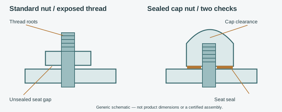
Specify male stud, female insert or another attachment exactly. Include thread diameter, pitch, usable engagement, blind-hole depth, stud projection and mounting-face dimensions. A matching nominal thread does not establish insert strength, bond capacity or tightening torque. Where a rigid stand-off is required instead, compare spacer and threaded stand-off connections.
Check the bolt's projection after bracket and washer thickness are accounted for. A bolt that bottoms in a blind insert may appear tight without clamping the bracket; it may also damage the insert or surrounding rubber. Too little engagement presents a different failure route. Use supplier dimensions and instructions rather than inventing a minimum engagement rule.
Avoid twisting the rubber while tightening a nut or screw. Use the intended wrenching feature and support the assembly as instructed; do not grip and distort the elastomer to obtain torque. Align contacting parts so the buffer is loaded in its approved direction, without unintended sideways force or permanent preload beyond its specification.
The supporting bracket needs its own mechanical and cleaning assessment. Our welded and threaded mounting-plate guide covers that interface. Do not cover a poor mounting connection with rubber and assume it becomes cleanable or mechanically adequate.
Hygienic versions: inspect the rubber-to-metal boundary
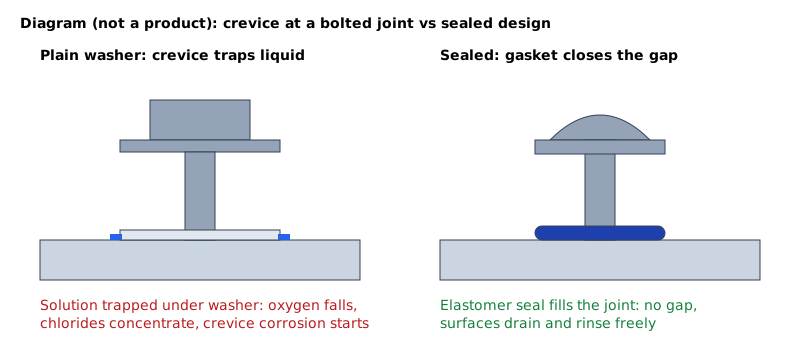
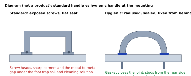
The product-contact zone touches food; a splash zone receives product or cleaning spray. Identify foreseeable transfer rather than assuming every rubber part in a food plant is in food contact. Harborage points are gaps where residue remains through cleaning; inspect the bond edge, insert opening and bracket seat.
Look for accessible mounting faces, intact bond edges and surfaces that shed liquid. A cleanable exterior does not eliminate residue behind a compressed rubber shoulder. State whether the buffer must be removed for cleaning and how it can be removed safely without disturbing unsupported equipment. COP, or cleaning out of place, may suit removable parts; an installed bumper is not automatically cleanable by CIP, or cleaning in place.
EN 1672-2 and EN ISO 14159 provide machine-hygiene references, not compound or mount capacities. EHEDG certifies specific equipment designs, not rubber families or companies. 3-A Symbol authorization follows Third Party Verification. Both are voluntary; use the design-certificate scope guide when certification is claimed. No certificate for another NHK component is transferred to a buffer here.
EC 1935/2004 covers food-contact materials within its scope. EU 10/2011 applies to plastics, not rubber indiscriminately. FDA 21 CFR 177.2600 addresses rubber articles intended for repeated use; it is not an FDA-issued approval of vibration performance. Food-contact evidence, cleaning compatibility and hygienic geometry must be checked separately.
Example: a washed guard-door stop
Assumptions: a guard door contacts a threaded rubber bumper and is foam-cleaned with the surrounding machine. Moving mass, closing speed, stroke and compound data are not supplied. This is an illustrative review, not an NHK field case or test.
The engineer records impact duty and permitted travel, then checks thread engagement using the bracket drawing. The hygiene team inspects the insert opening and bond edge after the proposed cleaning procedure. Stainless internal threads remain useful connection information, but cannot establish energy capacity or chemical compatibility. The stop is accepted only after the supplied variant's evidence and installation checks are resolved; no successful test result is assumed.
Inspection, failure symptoms and RFQ wording
| Symptom | Check before replacement | Action |
|---|---|---|
| Cracking, swelling or tackiness | Compound, chemicals, temperature and recent cleaning changes | Remove compromised parts safely; confirm replacement compatibility |
| Rubber separates from metal | Tension, shear, twist, impact and bond exposure | Investigate load path and retention; do not simply increase bolt torque |
| Joint loosens despite tightening | Bottoming, engagement, bracket seating and insert condition | Correct the connection using documented limits |
| Machine moves or alignment changes | Load distribution, creep, damage and operating excitation | Reassess support and dynamic requirements |
| Residue remains around the base | Bond edge, seat, drainage and cleaning access | Correct access or choose a different mounting arrangement |
Isolate machinery and support attached loads before removing mounts. Inspect after cleaning and at intervals based on duty and supplier instructions. The migrated machine-part hygiene and zone guide gives the wider installation context.
Copyable RFQ: “Identify the buffer variant, compound, metal parts and attachment. Confirm approved load directions, force-deflection limits and impact or dynamic data for the stated duty. Provide usable thread engagement, blind-hole depth, tightening instructions and cleaning limits for rubber, bond and metal. Supply applicable food-contact evidence or design certificates for the exact variant and intended conditions.”
Attach the load cases, allowed motion, frequency range when applicable, mounting drawing, cleaning cycle, required documents, quantity and delivery country. The buyer's component specification guides support that purchasing step.
NHK's machinery-component catalog names internal-thread and stud buffer variants as browsing labels, not approved construction or material specifications. Exact compound, load, dimensions, cleaning limits and certificate coverage need variant-level confirmation. Send the application so an NHK technician can suggest a component and prepare a quote; no response time, stock or performance guarantee is asserted.