Caster brakes are parking mechanisms, not a substitute for a complete machine-support assessment. Castor brakes is the British spelling; this guide uses US spelling. Start with the industrial caster selection and load guide for the rolling assembly, then choose what must be restrained when the machine stops.
Wheel brake vs total lock vs directional lock vs floor lock
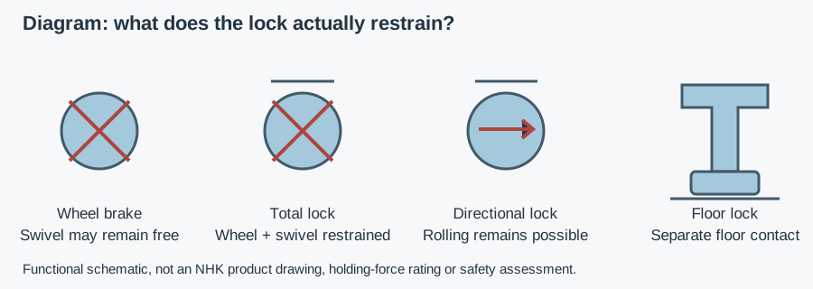
Specify the function rather than asking only for “brake casters.” Two pedals can operate different mechanisms. Floor lock casters may describe a cart fitted with a separate lock, not a caster with an integrated load-bearing foot. Obtain a drawing and identify the operating load path before comparing products.
| Mechanism | What it restrains | What it does not establish | Food-machine selection check |
|---|---|---|---|
| Wheel brake | Wheel rotation | Swivel restraint, leveling or no sliding | Does residual swivel motion affect parking or alignment? |
| Total lock | Wheel rotation and swivel movement | Rigid support, anchoring or a universal holding force | Confirm both functions engage and remain cleanable |
| Directional lock | Swivel orientation for travel | Prevention of rolling | Use for steering; provide separate parking restraint |
| Separate floor lock | Movement through floor-pad contact | Jacking, leveling or rated support unless explicitly designed for it | Pad reach, floor condition, clearance and instructions |
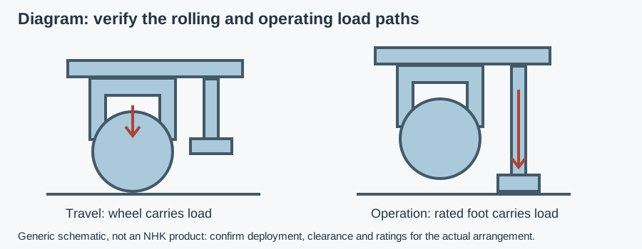
| Leveling caster | Load support through deployed foot, where rated | Suitability of every integrated design for cleaning or uplift | Verify foot rating, adjustment and wheel unloading procedure |
| Separate leveling feet | Defined operating support, where correctly selected | Automatic anchoring or restraint against every force | Check support loads, attachment and anchoring requirements |
Send the floor and restraint requirements for a component recommendation
Choose a wheel brake when its function and documented limits meet the parking requirement despite remaining swivel movement. Consider total lock where swivel motion must also be restrained. Choose a directional lock for controlled travel, not for stopping. If process stability requires the machine to operate on feet, do not keep adding brakes to avoid defining that support requirement.
Floor locks: floor contact is not a load rating
A typical separate floor lock deploys a pad against the floor while the wheels continue supporting the cart. Contact creates resistance to movement; it does not necessarily create a rated lifting or support function. Some products have different arrangements, so follow their actual instructions rather than inferring capabilities from the name “floor lock brake.”
Deploy a floor lock only when stationary and according to its instructions; it is not a service brake for slowing a moving cart. Some manufacturers limit their devices to level surfaces. Do not extend that product's permitted use to a slope or to another design.
Match mounting height and pad travel to caster height, tread wear and the floor beneath the parked equipment. A pad that fails to reach the floor cannot restrain effectively; excessive travel or interference may prevent proper engagement. Check the device in both released and engaged positions, including clearance over drains and thresholds.
Do not use an ordinary floor lock to jack up a machine or hold a raised load. For service work, isolate energy and provide appropriate rated support; brake engagement alone does not establish that removing a caster is safe. If the product is intended to lift or support load, require its instructions and rating explicitly rather than generalizing from another floor lock.
Parking, sliding and operating stability are different checks
Stopping wheel rotation does not prevent the tread from sliding across the floor. Likewise, a deployed pad relies on its contact conditions. Water, fats, cleaning residue, floor coatings and uneven contact can alter behavior. Holding performance depends on the actual tread or pad, load, geometry and applied forces; no universal wet-floor holding value is asserted here.
Use the wheel-tread and floor-protection comparison to separate material selection from restraint performance. A tread chosen for quiet travel or floor protection still needs its own parking assessment.
Identify whether the machine is parked unattended, positioned during changeover or expected to remain aligned while running. Account for operator pushes, connected hoses, process reactions and the center of gravity. A restraint that meets a parking requirement may not provide acceptable stiffness for a precision transfer, weighing operation or vibrating machine.
Slopes and foreseeable movement require a machine-level assessment and the manufacturer's instructions. Do not establish a safe slope by pushing an unrestrained loaded machine downhill. Plan any loaded test with controlled forces, a secure test area and independent measures against runaway movement. Reject an unsupported holding claim rather than improvising a hazardous test.
When leveling feet or leveling casters are better
The mobility versus fixed-support comparison separates occasional repositioning from operating support. Brakes leave load in the wheels, axle and swivel assembly, including their compliance and play. A correctly selected foot can create a different support path, but only when installed and loaded as intended.
For an integrated leveling caster, verify whether its foot is designed to take the full stated operating load and how to deploy it. Check that adjustment does not leave an unintended wheel/foot load split or a foot outside its permitted range. The leveling mechanism adds interfaces that still need cleaning. The combined wheel-and-foot deployment checks cover those two support states and adjustment interfaces.
Where anchoring, uplift resistance or larger operating reactions matter, use the fixed-support load and anchoring guide and the machine designer's load cases. “Leveling” does not automatically mean “anchored.” On existing machines, the migrated machine-feet stability and vibration guide explains the broader support-system decision.
Hygiene of the brake mechanism and floor pad
Brake pedals, springs, tread-contact parts and swivel gaps can form harborage points—places where residue survives cleaning. Check access with the lock engaged and released. A clean outer pedal does not establish that spray reaches underneath it or behind the spring. Arrange safe access without exposing personnel to unexpected machine movement.
For floor locks, inspect the pad edge, floor-facing surface, deployment linkage and bracket seat. The released pad must not create an inaccessible residue pocket. Self-draining surfaces shed liquid rather than retain it; a recess filled with wash water needs a design or cleaning solution. Check whether dismantling is required and how it can be done without removing needed restraint.
A splash zone receives product or cleaning spray; a non-product-contact floor device can still carry residue between areas. Select metals, pad compounds and any seals against the real cleaning chemicals, concentration, temperature and contact time. The complete stainless caster washdown guide separates the material of each assembly part from its cleaning suitability.
Food-contact scope depends on intended contact and foreseeable transfer, not merely installation in a food plant. EC 1935/2004 covers materials within that scope; EU 10/2011 applies to plastics and FDA 21 CFR 177.2600 to applicable rubber articles for repeated use. A compound declaration does not establish braking performance. Similarly, IP67 is an immersion test, not a washdown rating, and ingress evidence does not establish hygiene or holding force.
EHEDG certifies specific designs; 3-A Symbol authorization follows Third Party Verification. Both are voluntary. Use the hygienic-design certificate scope guide before requiring or accepting a certificate for a particular mechanism. No NHK certificate for a bearing, foot or another component is transferred to a brake or floor lock.
Installation and acceptance: six checkpoints
- Define the required function. Record wheel restraint, swivel restraint, steering, floor contact or operating support separately; do not accept a pedal description as the specification.
- Confirm mounting. Check drawing, fasteners, frame strength, deployment height and travel against supplier instructions. Do not invent tightening torque or pad preload.
- Check access and clearance. Verify pedal reach without placing the operator beneath equipment; check wheels, feet, floor-lock pad and released clearance through the travel route.
- Test function safely. Under an approved loaded procedure, confirm engagement, release and restraint. Check both wheel and swivel functions on a total lock, not merely pedal movement.
- Inspect after cleaning. Check residue, corrosion, pad or tread damage, sticky linkages and incomplete engagement. Restore the required restraint while inspecting alternate positions.
- Record acceptance and maintenance. Keep baseline findings and supplier limits. Set inspection intervals from duty and instructions, not an invented weekly rule.
Example: mobile packing table on a wet route
Assumptions: a packing table moves for cleaning and is parked during production. Its floor can be wet after rinsing; brake type and holding limits are undocumented. This is a hypothetical assessment, not an NHK case or test.
The engineer first decides whether production needs fixed support or only parking restraint. A directional lock is excluded as the sole parking device because rolling remains possible. Total locks and a separate floor lock remain candidates only after contact, mounting, cleaning access and documented limits are checked. If process alignment needs a foot-supported load path, the support arrangement is reconsidered instead of assuming more pedals will solve the problem.
Fault checks before returning to service
| Symptom | Check | Action |
|---|---|---|
| Pedal engages but equipment moves | Wheel rotation, swivel motion and floor sliding separately | Confirm the required function; remove from use if restraint is inadequate |
| Floor pad does not reach | Mounting height, tread wear, pad travel and local floor level | Correct installation against instructions; do not improvise extensions |
| Lock will not release fully | Residue, bent linkage, damaged spring or interference | Isolate and repair; check released travel clearance |
| Machine rocks despite locked wheels | Unequal support contact and compliance | Reassess operating support rather than increasing pedal force |
Do not defeat a spring or force a sticky mechanism back into service. Replacement must match the specified assembly and cleaning conditions; a similar-looking pedal does not establish equivalent restraint.
RFQ: what to send and what to request
Send machine type and loaded mass, support layout, wheel diameter and tread, travel route, floor material and condition, slopes, parking and operating forces, cleaning cycle, mounting drawing, pedal-access constraints and required documents. Include quantity and delivery country; identify known part codes when asking for a quote.
Copyable specification: “Confirm the supplied mechanism's wheel, swivel, steering or floor-contact function and its application limits. Provide mounting height, deployment travel, clearances and cleaning instructions. State holding-test conditions where claimed. Identify pad/tread materials and required maintenance. Any load-support rating or design certificate must cover the exact supplied variant.”
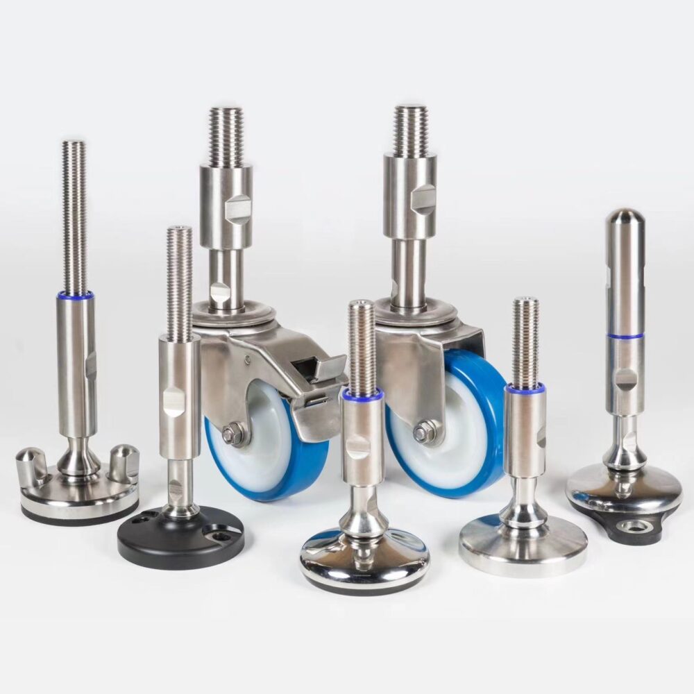
The buyer's component specification guides provide wider purchasing context. NHK's stainless caster range for brake-configuration enquiries is the product-browsing path; floor-lock availability and all holding limits need separate confirmation. An NHK technician can suggest an appropriate component and prepare a quote from the application details; no stock, response time or performance guarantee is asserted.