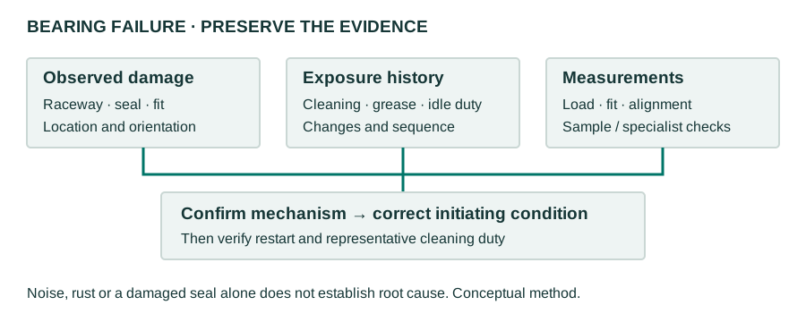
Shaft tolerance for insert bearings is the permitted size variation of the shaft seat selected for the actual insert, locking system and duty. A mechanically locked insert can use a sliding assembly fit where a conventional inner ring might require interference. That does not mean a worn or poorly shaped shaft is acceptable. Start with the bearing failure investigation framework if damage already exists; this guide addresses fit selection and acceptance before installation.
Shaft fit for bearing units: identify the locking system first
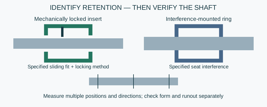
“Insert bearing” describes a bearing arranged for a mounted unit, often with an extended inner ring and a spherical outer surface. Its shaft connection is a separate choice from its ability to align in the housing. Identify the complete designation and locking instructions before choosing a drawing tolerance.
| Connection | How shaft retention is achieved | Fit-selection decision | What to check |
|---|---|---|---|
| Set-screw insert | Screws secure the extended inner ring to the shaft | Use the insert manufacturer's shaft recommendation for load, speed and duty | Shaft size and form, screw contact, retention and permitted thrust |
| Eccentric-collar insert | Eccentric engagement locks the collar and inner ring to the shaft | Confirm rotation direction and whether reversals are permitted | Collar seating, locking direction and the specified securing procedure |
| Concentric clamp or sleeve arrangement | A defined clamping system retains the inner ring | Use that system's shaft and assembly requirements, not a set-screw table | Required shaft geometry, tightening method and axial location |
| Conventional interference-mounted inner ring | Interference between shaft and ring provides the required seat connection | Select the fit for ring loading, bearing type and clearance requirements | Dimensional fit, assembly method and remaining internal clearance |
Send your application data and get a component recommendation
Manufacturer insert-bearing guidance supports mechanically locked designs using specified shaft tolerances without relying on a conventional interference fit alone. A looser permitted fit simplifies sliding assembly and replacement. It also leaves less geometric support if the shaft approaches the low limit, so the same recommendation may not apply at higher speed, heavier load or reversing duty.
Do not treat “fixed bearing” as an unambiguous opposite. A locating bearing controls axial shaft position; a non-locating arrangement permits axial movement. Either may use a particular seat fit. These functions must be designed separately. The migrated mounted-unit construction and locking guide supplies assembly context; obtain the exact shaft recommendation for the selected system.
Bearing fit tolerance: why loose and tight fits cause different problems
An interference fit can help prevent a ring creeping around its seat under rotating load. It may also expand an inner ring and change the bearing's internal clearance. Copying that conventional fit onto a sliding-fit insert can make assembly difficult or alter conditions the insert manufacturer did not intend. Do not hammer a reluctant insert into place to compensate for an unverified fit.
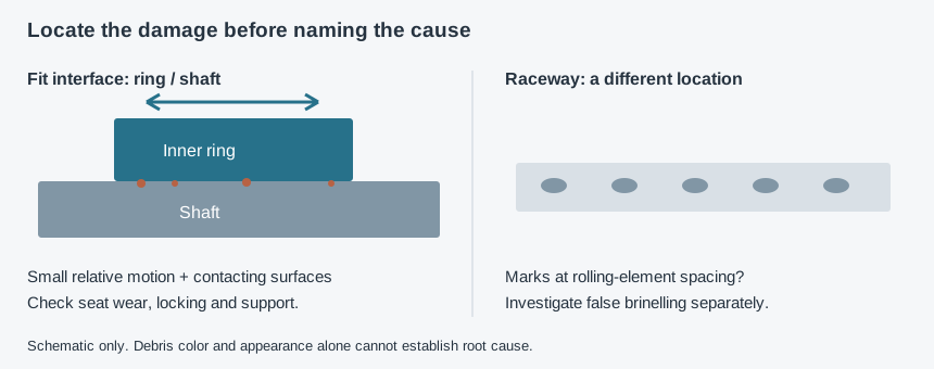
An excessively undersize shaft can let the inner ring sit off-centre, reduce support and allow movement despite apparent screw tightness. Possible consequences include runout, fretting, seat wear, vibration and loss of retention. More tightening torque does not restore the missing shaft material. Check screw marks and damaged seats rather than assuming that every loose unit only needs retightening.
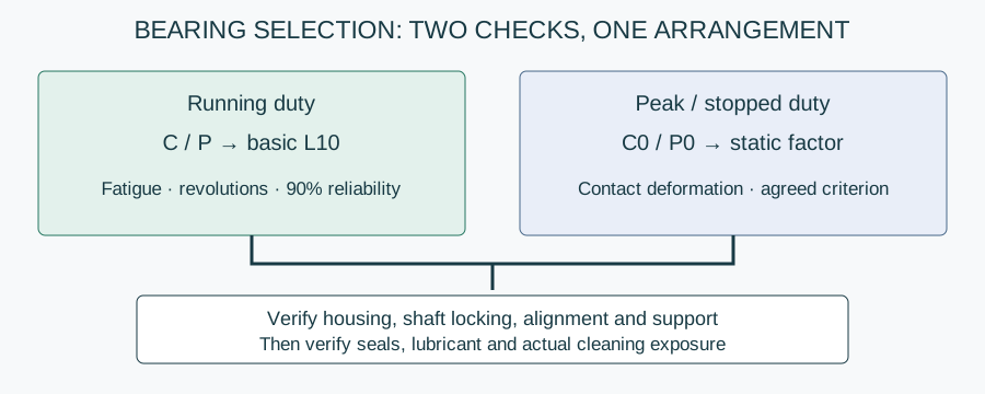
The two existing reliability spokes address different checks. Use the ring-seat movement diagnosis for wear or oxidised debris beneath the inner ring, and the fatigue-versus-peak-load assessment for capacity. A satisfactory fit does not approve the load calculation; a large dynamic rating does not approve a worn shaft.
h7 and h9 shaft tolerance: read the drawing correctly
Under ISO 286, lowercase letters denote shaft tolerance classes and uppercase letters denote hole classes. In h7 or h9, the lowercase h places the upper shaft size deviation at zero relative to nominal size. The number identifies the tolerance grade; IT9 has a wider tolerance interval than IT7 for the same applicable size step. The lower deviation is negative by that interval.
Therefore an h-class shaft is not intentionally oversized above nominal. However, the exact interval depends on nominal diameter and the applicable size range in ISO 286-2. Do not copy a micrometer limit from another diameter. H7 is a hole class, not the same shaft callout as h7, and a tolerance class alone does not establish the assembled fit without the mating bore's limits.
Neither h7 nor h9 is a universal answer for insert bearings. Manufacturer tables can vary by product family, speed, loading and locking construction. Use the recommended class or explicit limits for the identified item. This page intentionally supplies no blanket h9 recommendation and no numerical ISO tolerance table that could be mistaken for an NHK shaft specification.
Size tolerance also does not fully specify shaft form, runout or texture. A shaft can have individual diameters within the size band yet have unacceptable taper, ovality or alignment for the assembly. Document those requirements separately using the relevant drawing and measurement method. Do not apply the food-contact surface-roughness value to a bearing seat without a seat-specific basis.
Choose the shaft fit: six decisions before release
- Identify the insert and locking system. Record designation, bore type, collar or screws, intended mounting procedure and the source revision. If the locking type is uncertain, stop rather than selecting from housing shape alone.
- Describe the duty. Supply radial and axial loading, speed, starts, reversals, shock and running or idle vibration. Ask whether the suggested shaft range changes for those conditions.
- Confirm the fit basis. Obtain the manufacturer's recommended class or explicit size limits and translate the class at the correct nominal diameter using ISO 286 where applicable.
- Specify geometry and surface condition. Include required form, runout, texture, shoulders, chamfers and any seal-contact region. Separate seat requirements from general shaft tolerances.
- Define axial location and movement. Check how shaft growth and thrust are handled. Do not release an inner-ring lock as a makeshift floating arrangement; use a documented non-locating design where movement is required.
- Set acceptance and records. Name the inspection equipment, measurement positions, limits and decision rule. Require evidence before installation, including disposition of any repaired or out-of-limit seat.
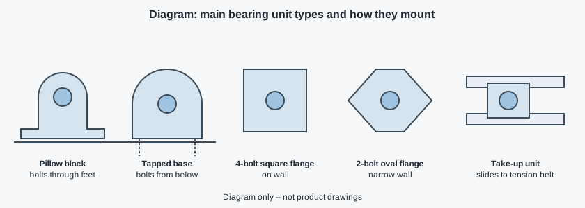
For housing geometry and support, use the base, flange and take-up comparison. Different housing footprints do not change an insert's shaft requirements automatically. Verify alignment and mounting rigidity as part of the same release, especially on flexible conveyor frames.
Measure the shaft seat: inspection and acceptance checklist
Isolate the machine and secure supported loads before inspection. Clean the seat without removing material to conceal wear. Remove loose contamination and identify burrs, scoring, corrosion, old screw indentations and raised metal. Compare the shaft drawing and actual insert instructions before measuring; nominal diameter is not an acceptance criterion.
Use a calibrated outside micrometer or other suitable dimensional instrument with resolution and uncertainty appropriate to the tolerance. A caliper reading can be useful for identification but is not automatically adequate for a narrow acceptance band. Check instrument condition and zero, and allow shaft and equipment to stabilise for the measurement conditions. Record temperature where it affects the result.
Measure at several axial positions over the seating length and in different angular directions. Record each reading rather than reporting only an average. Differences can indicate taper or ovality, but discrete two-point readings do not prove full cylindricity or eliminate lobing; use the specified form inspection when required. Check runout and shoulder geometry by their own methods.
Compare readings and required geometry checks with the released limits, applying the agreed uncertainty decision rule. Reject or hold for engineering disposition if a required limit is exceeded, a wear groove compromises support, or the measurement cannot establish conformity. Do not label a near-limit measurement acceptable merely by rounding it into the band. Keep the record with shaft identity and measurement locations.
Wrong-fit symptoms: inspect before changing the tolerance
| Finding | Possible fit-related explanation | Confirmation check | Action to agree |
|---|---|---|---|
| Inner ring moves or recurring loose lock | Undersize/worn seat, incorrect locking or unsupported motion | Dimensions, contact marks and locking procedure | Correct the demonstrated cause; obtain repair/replacement disposition |
| Debris beneath ring and local polishing | Small movement, fretting or coexisting corrosion | Damage location, fit, duty and exposure | Restore approved support/retention; investigate moisture separately |
| Insert will not slide into position | Oversize, raised metal, misalignment or wrong bore | Shaft/bore identity and clean measurements | Hold assembly; do not force through rolling elements |
| Runout or uneven running after locking | Poor geometry, eccentric seating or distorted support | Shaft form, runout, alignment and mounting | Correct geometry or arrangement; do not mask it with extra torque |
For the related corrosion cluster, compare the metal attack and cleaning-chemical checks when pitting or rust contributes to seat damage. For the related cleaning cluster, use the installed access and retained-residue assessment. A clean-looking external cover does not establish the condition beneath the inner ring.
Example: a worn conveyor seat before replacement
Example — hypothetical inspection, not NHK field data. Assume a conveyor insert uses set-screw locking and the drawing cites a manufacturer-approved h-class shaft seat. The old bearing has debris beneath its inner ring. The actual nominal diameter, tolerance grade, load and measured sizes have not been supplied, so no numerical acceptance or repair is assumed.
The engineer records measurements at multiple axial and angular positions, checks raised screw marks and compares them with the correct diameter-specific limits. A locally undersize reading requires a hold even if the average diameter appears acceptable. In-limit sizes with continuing movement require checks of locking instructions, support, runout and duty rather than automatic machining to a tighter class.
If a shaft is replaced or repaired, obtain an approved drawing and remeasure the complete seat before fitting the new unit. Do not use retaining compound, uncontrolled peening or additional screws to hide the condition. The example gives a decision route, not a successful repair claim or a universal workshop method.
Specification and enquiry: send the fit evidence
Copy and complete: “Insert designation and locking type: __. Shaft drawing, nominal diameter and released size limits: __. Individual measurements, locations, equipment and uncertainty basis: __. Form, runout, texture and seat condition: __. Load, speed, reversals, shock and vibration: __. Axial location and intended expansion movement: __. Zone, cleaning method, chemicals and temperature: __. Required material, mounting, cleaning and exact-design certificate documents: __. Quantity and delivery country: __.”
Send these details to NHK
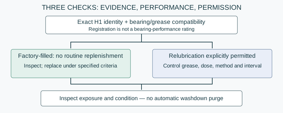
NHK lists sealed stainless units for shaft-and-locking enquiries. Send the evidence through this site's existing form so NHK can suggest a component and prepare a quote. Ask for the proposed designation's shaft limits and locking instructions; no NHK tolerance, torque, axial capacity or fit-repair approval is asserted here. Hygiene certification, where documented for a specific design, is not a shaft-fit approval; use the supplied-model and certificate verification guide for the document check.