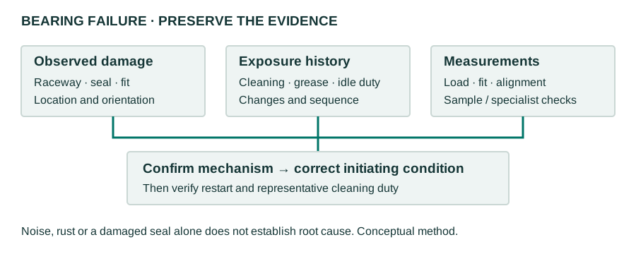
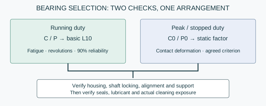
Static vs dynamic load rating compares two different bearing checks: contact deformation under a severe load and rolling-contact fatigue during rotation. A food conveyor may pass the fatigue calculation yet fail at a jam, a poorly supported housing or a water-damaged seal. Use the bearing damage and exposure investigation when actual failure evidence is available; this spoke explains the rating inputs before selecting a replacement.
Static vs dynamic load rating: which check governs?
Choose the check by the damage mechanism, not simply whether the shaft is moving. Rotating machinery still needs static assessment for peak loads. Stationary equipment does not gain a meaningful infinite service life by putting zero speed into an hours equation. The ratings belong to the identified bearing, not automatically to its housing or complete mounted assembly.
| Quantity | What it means | Use it for | What it does not establish |
|---|---|---|---|
| C, basic dynamic load rating | Constant-load fatigue reference for one million revolutions at 90% reliability under ISO 281 | Basic rating life with equivalent dynamic load P | Maximum permitted load, seal life or installed washdown endurance |
| C0, basic static load rating | Contact-stress/permanent-deformation reference under ISO 76 | Static assessment with equivalent static load P0 | Fatigue hours or a universal allowable shock load |
| P, equivalent dynamic load | Hypothetical load with the same modelled fatigue effect as the actual loading | L10 = (C/P)^p | A simple total of radial and axial forces |
| P0, equivalent static load | Load equivalent for the static contact assessment | Static safety factor s0 = C0/P0 | The same quantity as P in every load case |
Send your application data and get a component recommendation
Keep units consistent: use newtons throughout or kilonewtons throughout for a ratio. C and C0 are forces, not masses in kilograms. Record the bearing designation and data-sheet revision alongside both values. Never transfer a rating from a carbon-steel insert to a stainless insert merely because the bore and mounting dimensions match.
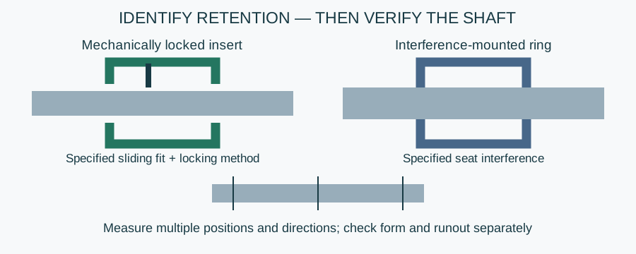
Check the shaft-seat limits and locking-system method separately: an acceptable fatigue result does not approve the shaft fit.
Bearing load capacity C and C0: turn machine forces into inputs
Start with a shaft free-body diagram. Radial force acts perpendicular to the shaft; axial force acts along it. Calculate bearing reactions from support spacing, overhung loads, belt or chain forces and drive reactions. Dividing machine weight by two bearings can be wrong when one support is closer to the load, the drive adds tension or a shaft carries thrust.
For combined loading, catalogue methods often express P using bearing-specific factors multiplying radial and axial loads. The factors, load-ratio thresholds and treatment of load direction come from the actual bearing instructions. Do not insert generic X and Y coefficients from another bearing series. Compute P0 separately using the manufacturer's static-equivalent-load method for each relevant peak case.
Check the whole load path as well. A permissible insert load does not authorize the same axial force through a set-screw lock or the same radial force in every housing direction. Bolts, mounting plate, shaft deflection and support rigidity have independent limits. The migrated mounted-unit sizing and installation guide adds the configuration context; confirm the proposed assembly's limits rather than selecting from its insert alone.
Basic dynamic load rating and the ISO 281 L10 method
ISO 281, Rolling bearings — Dynamic load ratings and rating life, gives the basic fatigue-life framework. The basic dynamic load rating is the reference load corresponding to one million revolutions at 90% reliability. It is not a load that the machine should routinely approach without checking the calculation's range of applicability and the supplier's other limits.
For constant equivalent dynamic load and constant speed:
- L10 = (C/P)^p, expressed in millions of revolutions.
- L10h = 1,000,000 × L10 / (60 × n), expressed in hours with n in revolutions per minute.
- p = 3 for ball bearings; p = 10/3 for roller bearings, following the basic ISO 281 method.
L10 is a population statistic: 90% of a sufficiently large group of identical bearings are expected to reach or exceed this basic fatigue life under the model's conditions. It is not average life, an individual guarantee or the planned replacement interval. Specify a different reliability requirement explicitly; do not silently relabel a basic L10 result as a higher-reliability estimate.
Basic life does not incorporate lubrication and contamination adjustment factors. Modified rating-life assessment can consider additional conditions and reliability, but requires the applicable method and verified inputs. ISO 281's life calculation does not cover wear, corrosion or electrical erosion. Keep the distinction between a calculation and an observed maintenance interval visible in every report.
Example: bearing life calculation L10 with stated assumptions
Example — hypothetical calculation, not NHK product data or field performance. Assume a ball bearing, constant equivalent dynamic load P = 2 kN, assumed C = 20 kN and constant shaft speed n = 150 rpm. Assume the bearing-specific loading method is applicable, normal alignment and suitable lubrication; no life-modification factor is applied. These assumed values do not identify an available unit.
- Calculate C/P = 20/2 = 10.
- Calculate L10 = 10³ = 1,000 million revolutions.
- Convert to hours: L10h = 1,000,000 × 1,000 / (60 × 150) = 111,111 hours, rounded.
- Check sensitivity: if P doubles to 4 kN while C and speed remain unchanged, L10 becomes 5³ = 125 million revolutions, or 13,889 hours, rounded.
- Keep the static check separate. Assume C0 = 12 kN and an independently calculated peak P0 = 8 kN. Then s0 = 12/8 = 1.5. This is a calculated ratio, not approval of the application.
The doubling of load reduces modelled ball-bearing fatigue life by a factor of eight. That sensitivity is a reason to measure tension and peak duty carefully, not a promise that reducing tension produces an eightfold field-life improvement. The static factor needs an agreed acceptance criterion, and the housing and shaft locking still need verification.
Static rating: stopped shafts, shock and low-speed duty
ISO 76, Rolling bearings — Static load ratings, bases C0 on contact stress at the most heavily loaded rolling-element/raceway contact. The associated total permanent deformation is approximately 0.0001 of the rolling-element diameter under the standard's assumptions, as explained in manufacturer static-selection guidance. That reference deformation is not a general machine acceptance tolerance.
Assess static load for loaded standstill, very slow rotation or small oscillations, and severe peak events even during otherwise normal rotation. Record credible jam, impact, startup and handling cases. Use the relevant P0 to calculate s0 and obtain the required factor from the bearing manufacturer for the duty and consequences of indentation; no single safety factor fits every application.
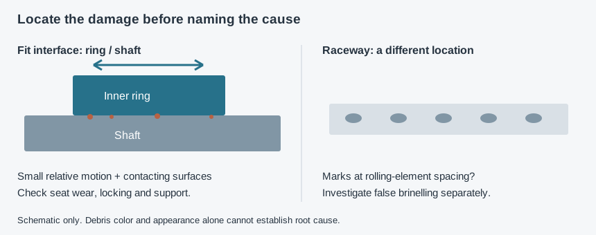
Installation force transmitted through rolling elements can produce damage independently of the running-life result. Idle vibration can produce false brinelling rather than a simple static overload. The fit-movement and idle-vibration distinction helps separate those mechanisms. A larger C0 does not repair a worn shaft seat or make an unsuitable mounting procedure acceptable.
Variable loads: do not hide peaks in an average
Split a changing duty cycle into segments with known load, speed and duration. Calculate each segment's equivalent dynamic load before combining fatigue exposure. Under an applicable basic cumulative-damage approach, use P_eq = [sum(P_i^p × N_i) / sum(N_i)]^(1/p), where N_i is revolutions in segment i. This weighting follows manufacturer rating-life guidance; it is not an arithmetic mean of forces.
For a constant speed, revolutions weighting reduces to time weighting of the powered loads. With changing speed it does not. Loaded dwell contributes no revolutions but still requires static and lubrication assessment. Separately preserve the maximum P0 and load direction: an equivalent fatigue load can obscure a short peak that governs indentation or housing strength. Ask for specialist review of uncertain impact loads and small-angle oscillation rather than forcing them into a constant-speed model.
Why washdown changes selection, not the definition of C
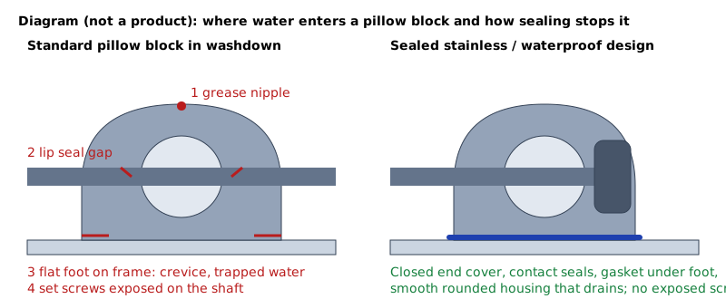
Water ingress can contaminate lubricant, reduce film effectiveness and promote corrosion; seal damage may then accelerate further ingress. A long basic fatigue-life result cannot validate that sealing path. There is no universal “washdown correction factor” to subtract from L10. Record the actual cleaning exposure and investigate it alongside mechanical loading.
Check the incidental-contact evidence and controlled lubrication method before translating a fatigue estimate into a maintenance plan.
For the related corrosion cluster, use the chloride exposure and corrosion identification checks. For the related cleaning cluster, use the installed cleaning-access assessment. Avoid hidden mounting gaps that retain liquid, and do not reduce the plant's sanitation requirements without an agreed hygiene assessment.
The migrated waterproof-unit seal and cleaning inspection route addresses the surrounding exposure. IP67 documents dust and temporary immersion conditions under IEC 60529, not high-pressure washdown or chemical compatibility. Specify evidence for the exact installed assembly, seal compound, cleaning method and permitted lubrication intervention rather than relying on an IP label alone.
Selection and inspection: release a complete arrangement
- Identify the duty. Record radial/axial reactions, speed, reversals, running hours, loaded stops, vibration and credible shock cases at each position.
- Check two calculations. Document C, C0, P, P0, their sources and methods; report basic L10h and the static ratio against separately agreed criteria.
- Verify assembly limits. Check housing direction, fixing, locking and support, plus alignment and allowed axial movement. Reject a selection if a required limit or its basis is missing.
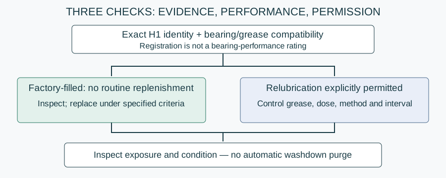
- Check environment and intervention. Specify zone, chemical exposure, seal path, grease identity and whether relubrication is permitted. Do not inject grease into a factory-filled unit without approval.
- Inspect installation. Use the specified force path and tightening instructions; check support contact, alignment, cover seating and free rotation after assembly.
- Set condition checks. Record baseline noise, vibration, temperature and leakage under representative duty, then inspect after cleaning. Confirm acceptance with the machine builder and hygiene team.
A fatigue calculation does not choose housing format. Compare the housing geometry and support decisions when the mounting arrangement changes. No dedicated bearing-load calculator is published on this site; this guide supplies the calculation method and evidence checklist, not a substitute for verified bearing-specific coefficients.
Specification and enquiry: send the calculation basis
Copy and complete: “Unit designation, shaft drawing and quantity: __. Radial/axial reactions, peak cases and P/P0 method: __. C/C0 data-sheet source: __. Speed, running/idle duty and reliability requirement: __. Basic L10h result and required static criterion: __. Housing, fixing, locking and alignment: __. Zone, washdown method, chemicals, concentration, temperature and rinse: __. Seals and lubrication strategy: __. Material, ingress/cleaning evidence and exact-design certificates required: __. Delivery country: __.”
Send these details to NHK
NHK lists a sealed stainless category for bearing configuration enquiries. Send the completed basis through this site's existing form so an NHK technician can suggest a component and prepare a quote. Ask for C/C0 and assembly limits for the proposed designation; this guide asserts no NHK load rating, available size, service-life guarantee or response time. Any claimed hygiene certificate must cover the specific design and does not establish fatigue life; use the exact-design document acceptance checklist for that separate review.