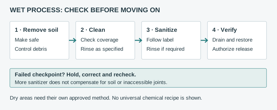
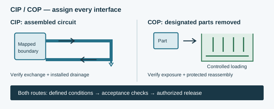
CIP vs COP compares cleaning an assembly in its operating position with removing specified parts for cleaning elsewhere. Clean in place, also called cleaning in place, keeps the defined circuit assembled; clean out of place opens selected interfaces so parts can be cleaned in a separate tank, cabinet or controlled workstation. Neither method is a synonym for sterilisation.
Use the cleaning sequence and release-evidence framework for the wider sanitation plan. This comparison addresses the design boundary: which surfaces a cycle actually reaches, which require removal, and how to demonstrate that the assembled machine can be returned to production.
Clean in place vs clean out of place: comparison
| Deciding question | CIP cleaning | COP cleaning |
|---|---|---|
| What stays assembled? | The specified process circuit, with documented cleaning configurations | Only the equipment remaining in place; designated parts are removed |
| How is soil removed? | Controlled circulation or spray coverage on intended internal surfaces | Controlled immersion, spray or manual action on separated parts |
| Main design challenge | Delivery, drainage, branches, valve seats and seal interfaces | Access, safe removal, washer loading, part identification and reassembly |
| Typical use | Compatible pipework, vessels, pumps and valves designed for in-place cleaning | Removable nozzles, fittings, guards and parts needing direct access |
| Evidence needed | Circuit coverage, relevant parameter records and difficult-location checks | Approved loading arrangement, surface exposure and restoration checks |
| When it is unsuitable | Inaccessible uncleaned pockets or components outside the demonstrated boundary | Parts unsafe to remove, unsuitable for the washer or impractical to restore reliably |
Send your application data and get a component recommendation
The deciding question is not whether the plant owns a CIP skid. It is whether each surface has a defensible cleaning route. A machine may combine CIP internally, COP at removable product-contact parts and manual external cleaning. Record those boundaries on the same drawing so an unassigned interface cannot disappear between procedures.
When to choose CIP, COP or a mixed method
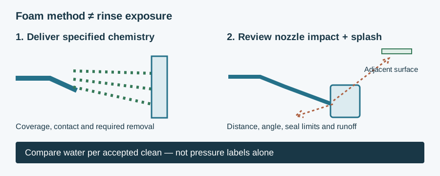
For external surfaces, use the foam-application and rinse-impact selection guide to review the separate washdown exposure.
Choose CIP when an installed circuit can deliver the approved process to all intended surfaces and drain as required. It is useful where repeated dismantling would be impractical, but circulation must be established through each relevant path. Long pipe runs, branches and changing valve states require engineering review rather than an assumption that liquid entering the inlet reaches everything.
Choose COP when removing a part provides the necessary exposure and inspection, and removal is safe and repeatable. Consider component weight, lifting access, retained hot liquid, sharp edges and the risk of damaging sealing faces. A removable part is not automatically washer-compatible: its cavity, material and basket orientation still need assessment.
Use a mixed method where a filler or process line has both a cleanable internal circuit and detachable items. Assign each interface to one method and define who cleans the remaining machine socket. For the architectural distinction, consult the enclosed-product and exposed-product interface comparison; enclosure alone does not establish CIP capability.
Moisture-sensitive production may require a different controlled approach. Neither CIP nor wet COP should be introduced just because it is easier to automate. Product hazards, moisture control, soil removal and authorised drying/release arrangements determine suitability. Compare total dismantling, handling, inspection and restoration work rather than promising that either method always takes less time.
Which components must be CIP-able?
Every product-contact surface assigned to the CIP boundary must be cleanable in its specified installed configuration. That can include vessel internals, piping, pump wetted parts, valve seats, instrument connections and process seals. Map surfaces exposed in production but isolated in cleaning, including bypasses, drains and sampling points. An interface outside the circuit needs its own documented method.
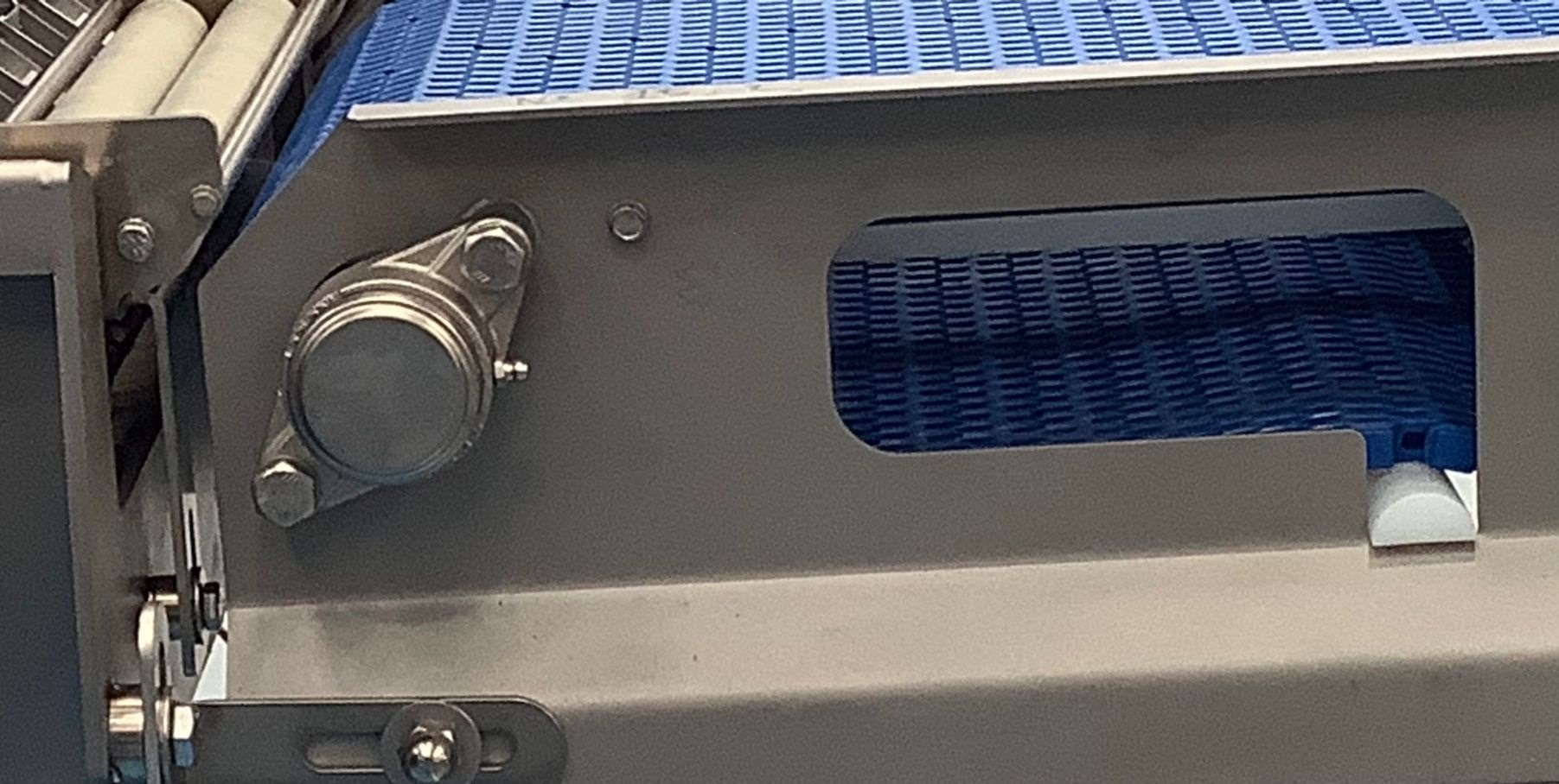
A product-contact zone touches food; a splash zone can receive product or cleaning liquid without intended contact. Bearings, levelling feet and frame fasteners outside a closed process are normally external-cleaning decisions, not parts through which CIP solution should circulate. Levelling feet still affect support orientation and cleaning access.
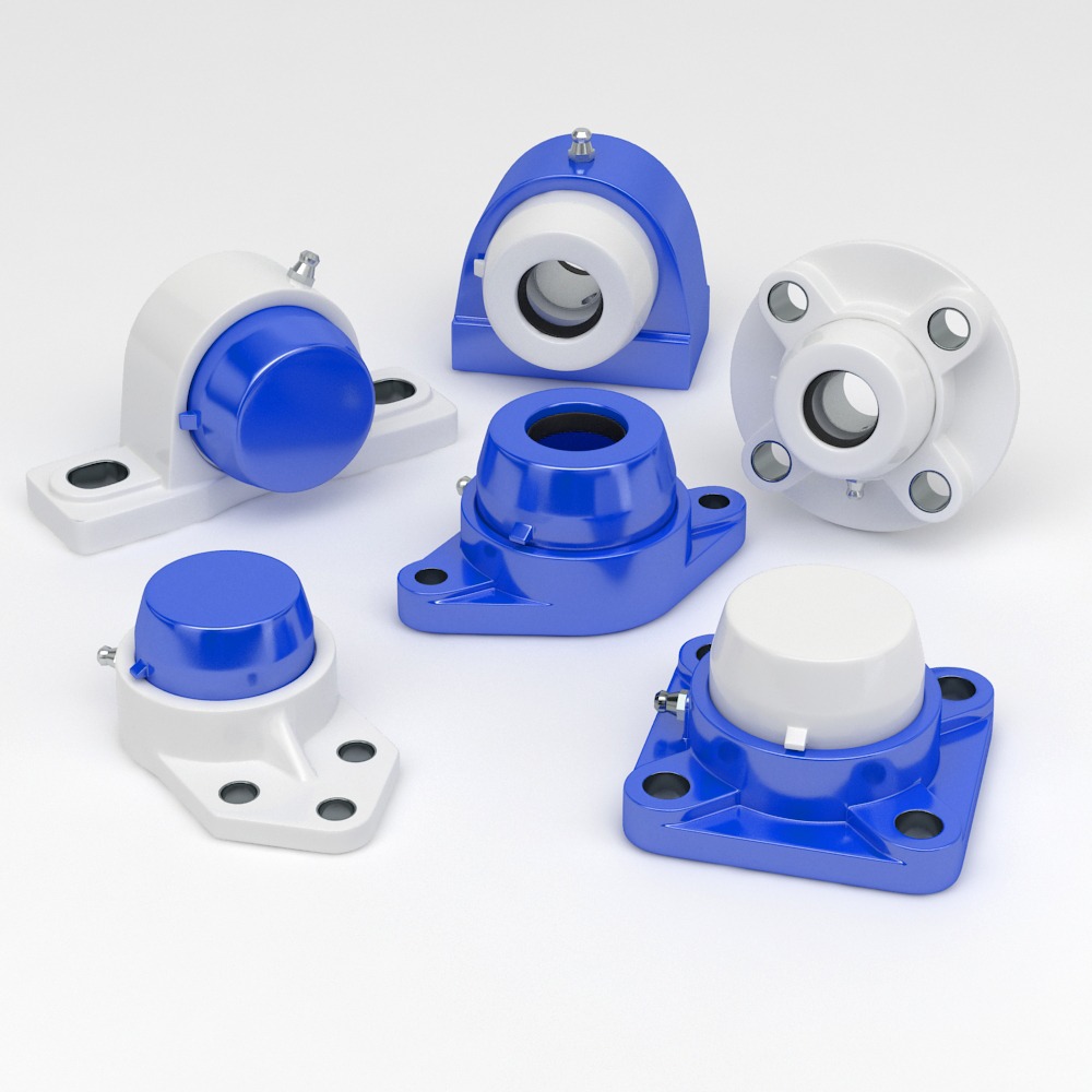
A seal protecting a lubricated bearing is not permission to pump detergent through that bearing. NHK lists sealed bearing units for external cleaning-duty review; obtain exact-item instructions and exposure limits. Use the related reliability cluster's washdown damage and evidence-preservation guide if water entry or lubricant leakage is already suspected.
Separate three questions in the equipment review: can the exposed surface be cleaned, can the assembly withstand the conditions, and can it prevent contamination crossing an interface? A positive answer to one does not establish the others. No category-level statement proves complete-machine cleanability or authorizes a cleaning recipe.
Drainability, dead legs and seals: inspect the installed geometry
Drainability means liquid can leave the intended system rather than remaining in pockets. Check the final orientation, pipe supports, low points, drain connections and valve positions. A drawing of an individual self-draining component does not show that the surrounding assembly drains. Consider retained rinse water and dilution as well as soil retention.
A dead leg is a branch or region with inadequate exchange during the cleaning process. A crevice is a narrow gap, while a dead space is a pocket where soil or liquid can remain. These can become harborage points: locations that retain contamination through normal cleaning. A short branch can still be poorly swept; do not apply a universal length-to-diameter ratio without an applicable design reference and evidence for the specific flow arrangement.
Inspect instrument stubs, capped ports, bypasses and valve cavities against the cleaning configuration. Document which valve positions expose relevant seats and which isolate product from cleaning solution. More pump flow cannot be assumed to correct a pocket that has no useful exchange. For practical installed-surface checks, use the cleanability and access assessment.
Check gasket compression, extrusion and seal seating against the assembly instructions. Specify the actual elastomer compound, not only an EPDM, FKM or silicone family name. Product fats, detergent, sanitiser, temperature and exposure duration all matter. Material compliance is separate from chemical compatibility and from cleanability.
Look for pitting, stained pockets and damaged sealing faces after cleaning. Use the related corrosion cluster's retained-cleaner and stainless-attack diagnosis before changing grade or concentration. Increasing temperature, pressure or chemical strength can damage a joint without correcting its cleaning access.
COP loading and reassembly: an acceptance checklist
COP shifts the engineering problem from circuit coverage to exposure and handling. A tank full of parts is not evidence of a successful process. Avoid nested items, closed cavities and contact points that shield surfaces from the intended cleaning action. Check that supports do not damage sealing faces and that small parts cannot be lost.
- Make safe and identify. Isolate the machine under its safety procedure; release stored energy and liquid safely. Identify each removed item and the machine opening left behind.
- Inspect before loading. Record visible soil, damage and inaccessible features. Segregate parts requiring replacement rather than sending damaged seals through another cycle.
- Load the approved arrangement. Use defined baskets, spacing and orientation. Confirm that intended surfaces are exposed and cavities can fill, exchange and drain where required.
- Run and record. Follow the approved chemical and equipment instructions. Record the relevant process parameters and deviations; immersion alone does not prove adequate action.
- Inspect, protect and restore. Apply the specified acceptance checks, prevent recontamination, account for parts and reinstall with correct seal seating, tightening and guarding. Hold the machine if acceptance is not met.
Include cleaning of the exposed machine interface, not only the removed part. Clean gloves or tools, storage and transport between washer and machine need controls appropriate to the hazard. The cleaning-shift obstacle and removal-access guide helps translate awkward handling into a design-change request.
CIP system validation and routine verification
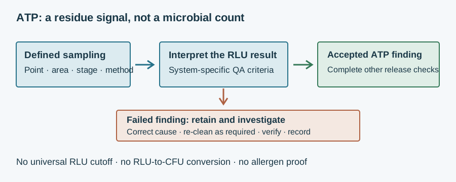
The rapid residue-test scope and sampling checks help distinguish an ATP finding from whole-circuit effectiveness evidence.
Cleaning validation establishes evidence that the defined process can achieve its intended result under specified conditions. Monitoring records whether it operated within its approved parameters; verification checks implementation and effectiveness. Define the soil, relevant allergen changeover, difficult locations, sampling method and acceptance criteria before deciding what constitutes success.
For CIP, retain circuit identification, valve sequence, cleaning configuration and appropriate flow, temperature, chemical-concentration and time evidence. A return-line conductivity reading can support concentration control when correctly applied and calibrated; it does not prove coverage at every valve seat. Tank spray coverage and removal of the relevant soil are different questions.
For COP, retain the loading arrangement, parts list, relevant cycle evidence and reassembly checks. Challenge the difficult surfaces, including those shielded by supports or inside cavities. An unloaded washer trial does not demonstrate a loaded process. Repeat the assessment as required when parts, products, chemistry or loading change.
Select residue, allergen-specific and microbiological methods according to the hazard. ATP is a residue indicator, not proof of pathogen elimination or allergen removal. Do not copy an arbitrary ATP threshold or call visual cleanliness sterility. CIP is not SIP—sterilisation in place—and neither a pump-running signal nor an EHEDG certificate validates the plant's cycle.
EHEDG Document 2 addresses assessment of in-place cleanability; Documents 8 and 50 address hygienic design principles and CIP installations. Apply their scope to the proposed equipment. For US human-food facilities in scope, 21 CFR 117.160 excludes sanitation and allergen controls from formal validation under that section; effective control and applicable verification remain necessary. Other sectors, jurisdictions and customer requirements differ.
Example: a transfer line with removable filler nozzles
Example — hypothetical assumptions, not NHK field data. A liquid-food line has a CIP-assigned transfer circuit, detachable filler nozzles and externally cleaned supports. A proposed change adds a capped sampling branch; no cleaning performance or successful outcome is assumed.
Review the new branch's exchange and drainage in the actual valve sequence. If its internal surfaces cannot be demonstrated cleanable in place, redesign the connection or assign a controlled removal/cleaning route. Define nozzle basket orientation and the cleaning of their mounting sockets. Keep support bearings outside the internal circuit and assess their external exposure separately.
Update drawings, parts-removal instructions, process evidence and difficult-location sampling before accepting the change. This is a boundary decision, not a reason to increase detergent throughout the line. It prevents a clean nozzle being restored onto an unclean socket or a completed CIP record concealing an unassessed branch.
Specification and enquiry: send the cleaning boundary
Copy and complete: “Component designation, drawing reference and quantity: __. Product-contact/splash/non-contact zone: __. Product, soil and allergen changeover: __. CIP boundary or COP removal and basket arrangement: __. Chemical identity, concentration, temperature, contact time, flow/pressure and frequency: __. Installed orientation, drainage, branch geometry and seal compound: __. Load, speed and duty: __. Acceptance, sampling and reassembly criteria: __. Required material, food-contact and exact-design documents: __. Delivery country: __.”
Send these details to NHK
Organise drawings and supporting evidence using the buyer’s application-document guides. Request applicable material declarations and exact-design certificates where claimed. EHEDG certifies specific equipment designs; 3-A Symbol authorisation follows Third Party Verification. Both are voluntary and neither replaces the installed cleaning assessment. NHK can recommend a component and prepare a quote; the machine builder and QA team retain procedure and release responsibility.