Drum motors place the drive inside the conveyor's rotating drum rather than beside it. This guide concentrates on the drive specification and its cleaning interfaces, not a product catalogue. The Conveyor and machine components overview provides the wider assembly context; select the conveyor concept before choosing its motor.
How a conveyor drum motor works
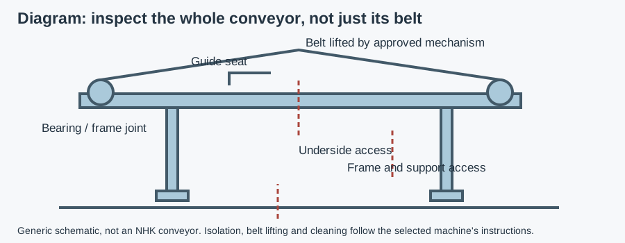
Check the frame and installed conveyor interfaces before fixing the drive arrangement.
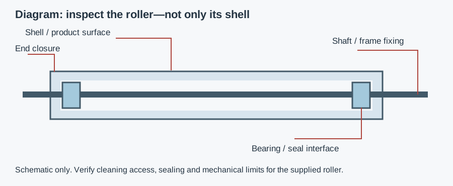
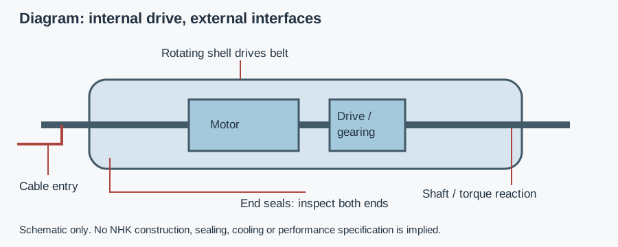
An internal motor and transmission turn the shell while shaft supports remain fixed to the conveyor frame. The frame connection reacts torque—the twisting action of the drive. The rotating shell moves the belt through friction, or through a positive-drive surface matched to the belt. Construction differs, so obtain the actual cross-section and installation instructions rather than treating the concept diagram as a product drawing.
For friction drive, grip depends on the belt and drum interface as well as the force pressing the belt around the drum. Positive-drive modular belts require compatible engagement geometry; a smooth shell is not interchangeable with a matched sprocket or profiled drive. An ordinary idler supports the belt without supplying drive torque; our roller shell, bearing and support-layout guide addresses that different role.
Drum motor vs external drive: deciding criteria
For the architecture decision, compare drum motor vs gear motor for food conveyors, including oil-free claims, cleaning boundaries and external-drive service access.
| Selection question | Drum motor: verify | External drive: verify |
|---|---|---|
| Space and cleaning | Internal drive can remove an external gearbox; check ends and supports | Gearbox, coupling, guards and brackets need access |
| Required motion | Belt pull, speed, startup and accumulation duty | Gear ratio, output torque and transmission duty |
| Thermal behavior | Cooling path, belt contact and low-speed restrictions | Motor/gearbox ventilation and environmental limits |
| Belt compatibility | Diameter, wrap and friction or positive-drive interface | Pulley and transmission designed for the same belt |
| Maintenance | Removal clearance, electrical disconnection and replacement procedure | Access to motor, gearbox, coupling and lubricant points |
| Washdown evidence | Seals, cable entry and complete variant | Each motor, gearbox, connection and enclosure |
Send the belt layout and cleaning conditions for a drive recommendation
Choose an internal drive when documented belt compatibility, thermal duty, mounting and service access support the installation. Keep an external drive as a candidate where maintenance access, a particular torque or control requirement, or the available cooling arrangement makes it more suitable. Neither architecture is automatically cleaner after installation or more efficient in every duty.
Selection: belt pull, speed, tension and startup
Effective belt pull is the tangential force needed to move the conveyor in its specified load case. Belt tension is not the same quantity: tight-side and slack-side tensions contribute to bearing and shaft loads, while their difference contributes to driving force in a friction system. Increasing tension to cure slipping can overload mechanical parts without resolving contamination or a mismatched interface.
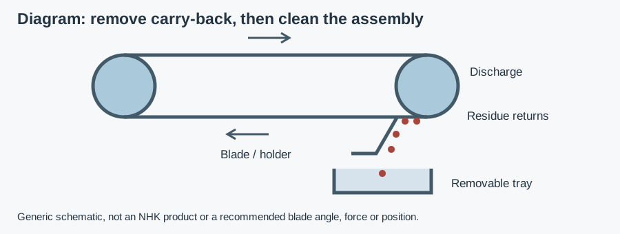
State payload, incline, belt and support friction, acceleration, accumulation and transfer forces. The conveyor designer should establish operating and startup cases using the belt supplier's method. Request continuous and intermittent limits for the proposed motor rather than selecting from a power label alone. A drive that runs a steady belt may still lack the required startup torque or exceed thermal limits during repeated starts. Include the blade contact and belt-cleaning arrangement when assessing the drive's operating conditions.
Specify required belt speed and its range, drum diameter and belt wrap—the angle over which the belt contacts the drum. Diameter affects belt bending and drive geometry; verify the belt manufacturer's limits. Include face length, shaft fixing, belt-tracking requirements and removal clearance. Do not assume a wider replacement drum has the same thermal or mechanical rating.
Heat removal and variable-speed operation
The motor produces heat inside an enclosure. Some drum-motor designs transfer heat through internal fluid and the shell, with the moving belt participating in heat removal; other constructions use different arrangements. Ask how the selected variant is cooled and whether it may run unloaded, without a belt or at low speed.
Record ambient conditions, product temperature, operating time, starts, stops and control mode. A variable-frequency drive changes speed but does not make every operating point permissible. Obtain the allowed speed range, torque limits, protection settings and wiring instructions for that motor. Include startup and shutdown when assessing the operating cycle.
Do not treat a protective trip as permission to keep restarting. Repeated overheating can indicate excessive duty, drag, wrong settings or insufficient cooling. Investigate the cause against supplier instructions. If a maintenance test requires operation without the normal belt contact, obtain approval for that test condition before running it.
Stainless steel drum motor: inspect the complete exterior
Stainless shell construction does not identify the alloys of shaft ends, fasteners or other exposed parts. Ask for each material and its cleaning limits, including the shell coating or drive covering where fitted. A closed shell can reduce external drivetrain parts, but end seals, cable glands and mounting brackets still create interfaces to inspect.
Map the product-contact zone, which touches food, and the splash zone, reached by product or cleaning spray. Belt contact does not automatically settle food-contact scope: assess foreseeable transfer and cleaning residues for the application. EC 1935/2004 applies to food-contact materials within scope; EU 10/2011 applies to plastics and FDA 21 CFR 177.2600 to applicable repeated-use rubber articles. Material evidence is not a motor performance rating.
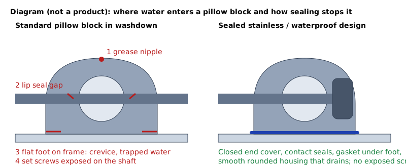
Look for harborage points—gaps that retain residue—beside end caps, shafts and bracket seats. Self-draining surfaces shed wash water rather than trap it. The side-guide cleaning-access guide helps assess neighboring conveyor interfaces, while the migrated sanitary component selection overview places the drive among the line's other parts.
IP69K, cleaning and what certification does not cover
IP ratings describe ingress tests, not hygiene certification. IP67 under IEC 60529 addresses temporary immersion; IP69K in ISO 20653 concerns hot high-pressure jets under specified test conditions. Ask which standard and exact variant were tested, and what restrictions apply to installation and cleaning. A label without its evidence cannot establish the suitability of the complete conveyor drive.
Record detergent and disinfectant, concentration, temperature, contact time, jet practice and drying. Test evidence does not automatically cover chemical attack, aging of seals or an improperly installed cable connector. Do not direct pressure jets at an interface outside the supplier's instructions. For the wider exposure assessment, use the combined water, chemical and temperature checklist.
EN 1672-2 and EN ISO 14159 provide machine-hygiene references. EHEDG certifies specific designs, not stainless steel or manufacturers. 3-A Symbol authorization follows Third Party Verification; both schemes are voluntary. No NHK drum-motor certificate, IP69K rating or seal specification is asserted here. A certificate for another component does not extend to the drive.
Installation and acceptance: six checks
- Isolate the machine. Follow energy-isolation procedures and secure belt tension and stored energy before removing a drive. An emergency stop alone is not a maintenance isolation procedure.
- Match parts to the drawing. Confirm shaft orientation, brackets, torque reaction, shell interface and cable exit. Do not improvise shaft clamping or force a misaligned drum into place.
- Set the belt correctly. Follow tension and tracking instructions. Verify clearance at edges and transfers rather than raising tension whenever tracking is poor.
- Complete electrical checks. Qualified personnel must follow supply, grounding, control and protection requirements for the selected motor and installation.
- Check operation safely. With guarding restored, verify direction, speed, tracking and behavior under the agreed load cases. Investigate drag or trips before accepting the drive.
- Check cleanability. After the prescribed cleaning procedure, inspect ends, cable entry and support faces for retained residue or damage. Record a baseline and service access.
For frame fasteners, use the sealed-joint and hygienic bolt specification guide. Where the drive is part of a process line, the food-equipment zone and selection guide helps identify the surrounding exposure and documentation requirements.
Example: a short washdown belt with intermittent starts
Assumptions: a short conveyor moves packaged products, starts frequently and is foam-cleaned and rinsed. Required pull, speed, cooling limits and electrical details have not been supplied. This is an illustrative selection review, not an NHK installation or measured test.
The engineer requests operating and startup cases, the belt's drive interface and the motor's thermal instructions. The cleaning team checks both ends and cable entry. A stainless internal drive remains a candidate only after those limits, mounting and removal access are resolved. No power, diameter or ingress rating is guessed, and no successful cleaning result is assumed from the shell material.
Copyable RFQ and the next purchasing step
“Confirm availability and suitability of a conveyor drive for the attached belt layout. State effective belt-pull and startup limits at the required speed, allowable belt tension, drive interface, thermal duty and control requirements. Identify exposed materials, seal and cable-entry construction, cleaning limits and mounting instructions. Supply any claimed ingress report or design certificate for the exact variant.”
Attach application and zone, belt data, load cases, speed range, incline, duty, ambient conditions, electrical supply, cleaning cycle and mounting drawing. Add requested documents, quantity and delivery country. The buyer's component specification guides provide the wider purchasing context; no dedicated drum-motor sizing tool currently exists on this site.
NHK's approved conveyor mounting and component range establishes the category, not a particular drum-motor offering. Send the layout so an NHK technician can confirm availability, suggest appropriate components and prepare a quote. No power, material grade, cooling design, capacity or delivery promise is inferred from that page.