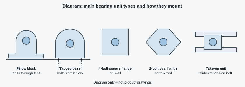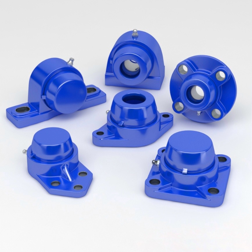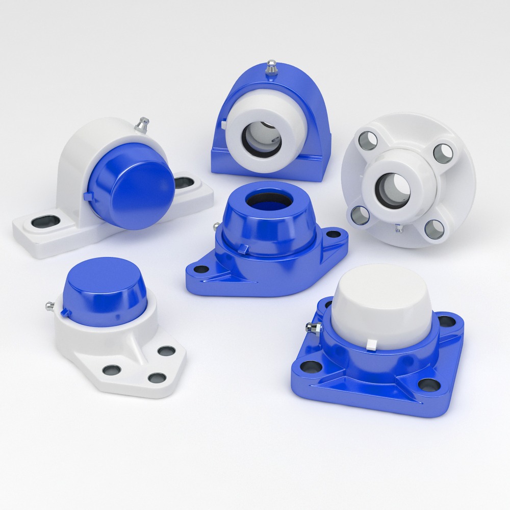
Bearing unit designations are identification codes, not replacement approvals. Start by separating the housing marking from the insert marking: a housing can accept bore options that its own number does not distinguish. This decoder covers common UC-unit conventions and NHK’s published housing families, then turns the marking into a replacement specification. For the mounting shapes behind the letters, use the bearing unit types overview.
How bearing unit designations are built
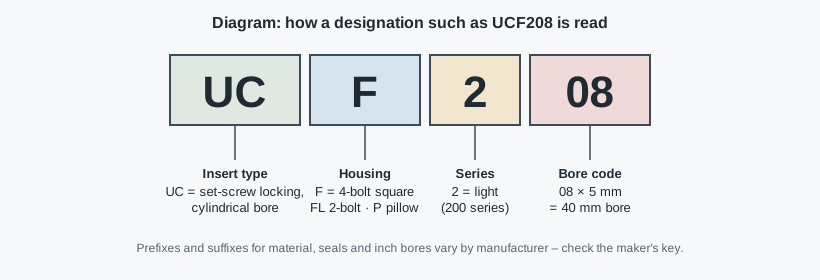
A mounted unit combines an insert, the rolling bearing that locks to the shaft, with a housing, the body attached to the frame. In common UC nomenclature, UCF208 combines a UC208 insert with an F208 housing. A label saying only F208 may be shorthand for a complete unit, but it can also mean the housing alone. Ask which is being offered.
| Code element | Common convention | What to verify |
|---|---|---|
| UC | Cylindrical-bore, set-screw insert | Exact insert and locking instructions |
| UK | Tapered-bore insert used with an adapter sleeve | Sleeve, shaft seat and complete assembly |
| UEL; other collar codes vary | Eccentric-collar insert family | Maker’s key and rotation requirements |
| P / F / FL and other letters | Housing mounting family | Mounting pattern and drawing |
| 2 in UC208 | 200-series size family | Do not infer a load rating from the digit |
| 08 in metric UC208 | Bore code: 08 × 5 = 40 mm | Metric convention, complete marking and suffix |
| Additional prefixes or suffixes | Material, covers, seals, lubrication or bore options | Meaning in that manufacturer’s catalogue |
Send your application data and get a component recommendation
The NTN Bearing Units Handbook separates bearing and housing part numbers and documents manufacturer differences. ISO 9628 and ISO 3228 address dimensions and tolerances within their scopes; neither makes every covered stainless, composite or proprietary assembly interchangeable. Preserve punctuation, spacing and suffixes when recording the original marking.
Housing letters: UCP vs UCF, FL, PA, FC, FB and T
These are common catalogue meanings, not a universal alphabet. Manufacturers may use different letters for a similar shape. PA is used for a compact or tapped-base pillow block in some catalogs; inspect the underside rather than assuming how it bolts down.
| Housing letters | Typical mounting family | Replacement checkpoint |
|---|---|---|
| P | Pillow block with base mounting | Shaft centre height and base bolt spacing |
| PA | Compact / tapped-base pillow block, maker-dependent | Threaded-hole arrangement and access below |
| F | Four-bolt square flange | Bolt square, mounting offset and face flatness |
| FL | Two-bolt oval or rhombic flange | Bolt line, load direction and available face area |
| FC | Round piloted / cartridge flange | Pilot diameter, depth and locating fit |
| FB | Three-bolt, often one-sided flange | Actual pattern, not just bolt count |
| T | Take-up housing moving in guides | Guide fit, adjustment travel and retention |
UCP vs UCF is mainly a mounting distinction: the P base sits on a surface parallel to the shaft; the F flange attaches to a surface perpendicular to it. The UC insert family can be shared, but changing housing format changes the frame interface. The flange mounting and load-direction guide helps select the pattern; the base-mounted bearing installation guide adds alignment and locking checks. Neither format is automatically stronger from its letters alone.
Metric bore codes, small-bore exceptions and inch suffixes
In the metric convention illustrated in NTN’s handbook, 00 = 10 mm, 01 = 12 mm, 02 = 15 mm and 03 = 17 mm. From 04 upward, the bore code is multiplied by 5 mm. These are insert-bore conventions, not a method for measuring the shaft from an unverified housing label.
| Metric insert code | Bore code | Bore under this convention |
|---|---|---|
| 204 | 04 | 20 mm |
| 205 | 05 | 25 mm |
| 206 | 06 | 30 mm |
| 207 | 07 | 35 mm |
| 208 | 08 | 40 mm |
| 210 | 10 | 50 mm |
For an FL206 bearing, FL commonly identifies an oval two-bolt housing; a metric UC206 insert is 30 mm under that convention. F205 and F207 housing references similarly suggest a size family, not proof of the bore actually installed. Nonstandard bores, miniature families and slash-marked sizes need the specific manufacturer’s table.
Inch codes are particularly easy to misread. NTN’s interchange table shows a 1½-inch bore as 08-108 in its convention and 08-24 in certain other makers’ conventions. That bore is 38.1 mm, not the metric 208 bore of 40 mm. A suffix in sixteenths cannot be assumed for every maker. Record the physical shaft measurement and units, then verify which insert fits the housing. For machining or accepting the seat, use the shaft-fit and locking-system checks; bore identification is not a tolerance specification.
NHK series: SP, SPA, SF, SFL, SFB, SFC and PPL
NHK’s published stainless housing families list SP, SPA, SF, SFL, SFB and SFC units with covers. The adjacent composite range uses different labels. The table records category identities only, not approved one-for-one equivalents.
| Mounting family | NHK stainless category label | NHK composite category label |
|---|---|---|
| Pillow block | SP | PPL |
| Tapped-base pillow block | SPA | PAPL |
| Four-hole square flange | SF | FPL |
| Two-hole oval flange | SFL | FLPL |
| Three-hole one-side flange | SFB | FBPL |
| Four-hole cartridge flange | SFC | FCPL |
NHK lists the PPL bearing unit in its IP54 composite housing range. PPL is not a bore size, and “PPL mm” is incomplete ordering information. Ask for the full size and shaft option. Do not infer that PL or S has the same meaning in another manufacturer’s catalogue.
Searches such as SP208 bearing, SF205 bearing, SFC210, SF206 and SF208 combine a recognizable family with an apparent size number. The inspected NHK category listings verify the family names, not every complete designation, its availability or its bore options. Send these markings as identification requests; do not publish a dimension or load table for them without the matching product drawing. The sealed-bearing application guide explains the environmental selection separately from the naming.
Find a stainless or hygienic equivalent in six checks
- Identify what is being replaced. Photograph housing, insert, collars and covers. Specify complete unit, housing only or insert only; retain every suffix.
- Measure the shaft and mounting interface. Record diameter and units, bolt centres, hole sizes, base height or mounting-face offset, and any locating pilot. Compare drawings at the same datums.
- Check axial space and locking. Covers and seals can extend beyond the old unit. Confirm shaft shoulders, screw access, collar clearance and whether the shaft ends or passes through.
- Recheck mechanical duty. Supply load direction, speed, reversing duty and shock exposure. Use the selected insert’s ratings and the housing’s permissible loads; material substitution does not preserve assembly capacity.
- Define cleaning exposure. Record chemicals, temperature, pressure and frequency. A splash zone is reached by spray without necessarily touching food. Check drainage and crevices, narrow joints where residues can remain.
- Agree the evidence before ordering. Obtain the exact drawing, material and lubricant identification, cleaning instructions and any required certificate scope. Reject an “equivalent” that does not resolve the measured interfaces.
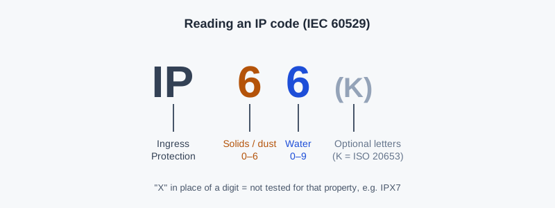
IP67 under IEC 60529 addresses temporary immersion; IP69K under ISO 20653 addresses hot high-pressure jets. Neither proves cleanability or chemical compatibility. Use the immersion-versus-jet requirement comparison to match test evidence to exposure, not to the apparent order of the numbers. A stainless code alone also does not establish an EHEDG-certified design.
Example: a housing marked F208 after washdown damage
Example (assumed situation, not NHK field data): maintenance records an F208 housing on a conveyor, but the insert marking includes an inch-bore option. The shaft measures 1½ inches. Ordering a metric UCF208 solely from the housing would produce the wrong bore.
The engineer requests a square flange replacement for that measured shaft, records the bolt pattern and mounting offset, checks cover clearance and supplies the cleaning regime. Use the belt-drive and support-interface checklist to place that bearing request in the conveyor layout. The supplier must confirm the exact assembly and drawing before purchase. The useful conclusion is not a universal stainless part number: it is a verified set of interfaces and service requirements.
Inspection mistakes and what to send in the RFQ
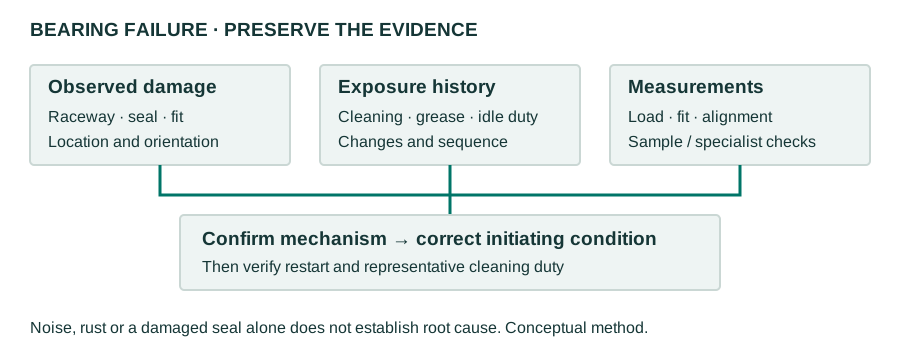
Look for a rubbed-off insert suffix, an eccentric collar mistaken for set-screw locking, or a pilot flange installed without a matching locating bore. Check for distorted mounting faces, slipping shaft seats and loose cover attachments. Replacing the code without addressing these conditions can repeat the damage.
Copyable RFQ: “Replacement for [maker and complete marking]. Required: [unit/housing/insert]. Shaft: [measured diameter and units]; locking: [type]. Mounting: [bolt centres, height/offset, pilot and drawing]. Clearance: [shaft end/through, cover space]. Duty: [loads, direction, speed]. Cleaning: [zone, chemicals, pressure, temperature, frequency]. Materials, lubricant and documents: [requirements]. Quantity and delivery country: [details].”
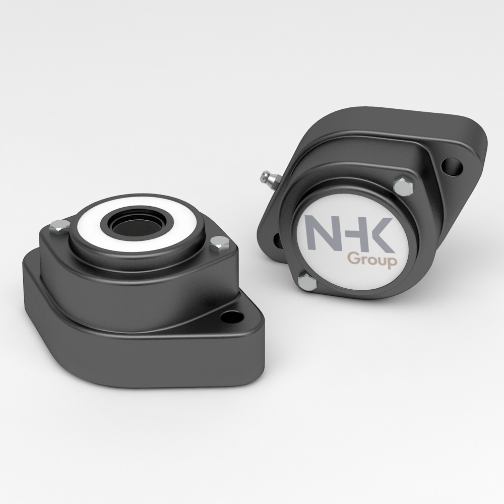
An NHK technician checks the identification and application information, suggests a component and sends a quote. For full technical data, use NHK’s product catalogue request; the listing is not a substitute for the exact replacement drawing. Before accepting any hygienic-certification claim, follow the certificate verification checklist for the specified design.