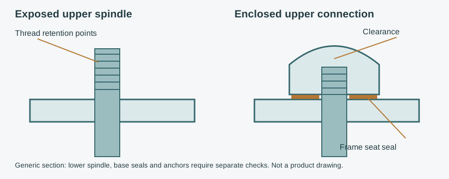
A hygienic top cover addresses the upper spindle-to-frame interface of a levelling foot, not its complete support design. Use the machine-foot selection and load-path guide for the support itself; this guide concentrates on enclosure, seating, adjustment and retrofit approval.
Hygienic top cover: identify the interface before ordering
A top cover may be called a spindle cover, top cap or thread enclosure. Names do not establish which part of the thread it closes. Mark the upper projection, frame seat, locking feature and lower spindle on the drawing. Identify whether the proposed design closes an end, seals a seat, surrounds a moving spindle or combines these functions.
| Interface or requirement | Establish before selection | Reject or resolve |
|---|---|---|
| Upper thread | Projection and thread form at operating height | Exposed thread beyond the enclosure |
| Frame seat | Approved contact footprint, surface and alignment | Seal crossing a slot, damaged face or incompatible curvature |
| Internal clearance | Usable enclosure depth at permitted settings | Spindle bottoming before proper seating |
| Adjustment and locking | How height is set and secured with the cover fitted | Cover blocks access or replaces an unverified locking function |
| Load path | Existing engagement and structural support arrangement | Assuming an enclosure raises the foot's rating |
| Material and seal | Exact grade/compound, cleaning exposure and replacement identity | Generic stainless or food-grade claims without limits |
| Existing cavity | Frame penetration, cleanliness and closure strategy | Hiding residue or leaving an open frame interior |
| Evidence | Exact design and installed configuration | Unmatched certificate or assumed universal retrofit fit |
Send the foot drawing and cleaning data for a cover recommendation
What thread enclosure and frame seals accomplish
Exposed thread roots and the gap around a spindle connection can retain product or cleaning residue. A crevice is a narrow gap that cleaning cannot reliably reach; a harborage point is a place where contamination survives the procedure. Covering the thread removes one exposed geometry, while sealing the seat addresses a separate ingress and retention route.
A cap placed over a dirty or unsealed connection may merely conceal the problem. Inspect and prepare the interface before enclosing it. A self-draining exterior releases liquid in its installed orientation rather than holding a pool. Check the underside and frame junction as well as the rounded top, and ensure drainage does not carry contamination toward product.
An integrated seal needs the intended mating face and assembly conditions. Ask how compression is controlled and which surfaces must seat. Do not invent a tightening torque or use a sealant bead to compensate for a missing engineered seal. An extra washer, reversed ring or unrelated replacement can create another interface rather than close the original one.
The cover does not establish the cleanliness of a hollow frame interior. If a penetration communicates with an inaccessible cavity, resolve the frame closure and inspection strategy. Do not put a smooth shell over that pathway and assume the entire connection has become hygienic.
Check the installed conveyor frame and cavity-closure details when the support connects to a conveying assembly.
Levelling foot top cover versus a complete hygienic foot
A top cover is an accessory or element of an assembly. It does not automatically enclose the lower exposed stem, seal a swivel joint, close the base-pad edge or address floor anchors. Review these interfaces separately. The foot terminology and design comparison distinguishes a height-adjustable support from a documented hygienic arrangement.
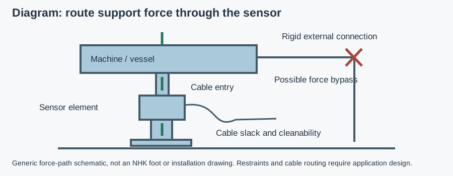
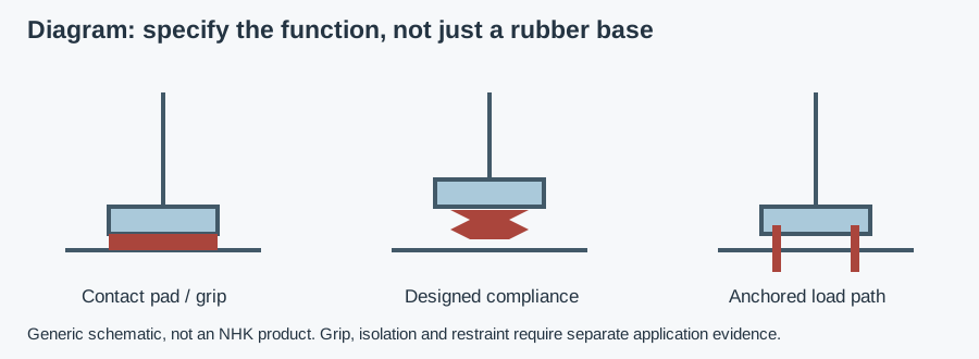
Keep the structural and sealing functions separate. The spindle, frame engagement, base and restraint must still carry the assessed forces; the cover is not a load calculation. Unless the manufacturer explicitly assigns it a mechanical role, do not use it as a substitute for a locknut or support feature. Changing engagement or locking to make a cover fit requires the machine builder's assessment.
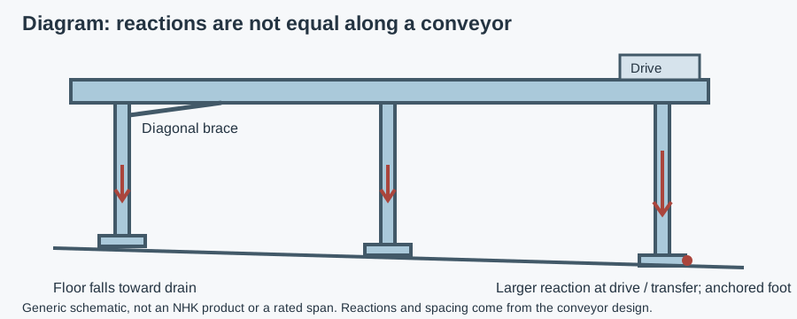
In a splash zone, product or cleaning spray reaches the assembly even when the foot never touches food. A protected non-contact location may permit a simpler enclosure, depending on contamination routes and cleaning. There is no blanket rule requiring this accessory under every machine. For complete stands, use the conveyor-leg reaction and mounting checks rather than assuming the cover specifies the leg.
Retrofitting covers: a five-gate decision method
- Identify the existing assembly. Obtain manufacturer, designation and drawings. Record thread diameter, pitch and form, upper projection, frame thickness and the existing height/locking settings. A photograph is helpful but not a dimensional approval.
- Assess the mating face. Determine whether the proposed seal footprint lies on an approved continuous surface. Inspect scratches, corrosion, slots, weld transitions and misalignment. If it cannot seat correctly, redesign the connection or replace the support assembly.
- Check the operating range. Compare clearance and enclosure across permitted settings, including the maximum upper projection. Confirm engagement and adjustment access stay within the original support limits. Shared thread size does not establish matching cap depth or sealing geometry.
- Confirm cleaning and service. Obtain actual chemical/temperature limits, seal identity and replacement instructions. Establish whether safe removal needs unloading or temporary machine support. A cover that cannot be inspected when required may be the wrong retrofit.
- Approve evidence and change control. Match any certificate to the cover and installed configuration. Record the revised bill of materials, adjustment procedure and inspection locations. Reject an assumed certified combination until its scope and mounting conditions are documented.
If one gate fails, do not work around it by removing a locknut, reducing engagement or increasing tightening force. Consider an approved compatible assembly or relocation of the interface instead. The migrated machine-foot reliability and inspection guide places this change in the wider maintenance plan.
Materials, cleaning chemistry and seal replacement
AISI 304 and 316L are common stainless candidates, not asserted NHK cover specifications. 316L generally improves resistance to chloride pitting relative to 304, but retained chemicals can attack either. Record detergent and disinfectant, concentration, temperature, contact time, rinsing and drying. Specify the actual surface condition as well as the alloy.
EPDM, FKM and VMQ silicone are elastomer families, not universal compatibility ratings. Ask for the supplied compound's documented behaviour under the combined product and cleaning exposure. Mechanical fit and chemical resistance must both be satisfactory. The migrated harsh-environment component guide supplies exposure context; use it without inferring an NHK alloy or temperature limit.
Food-contact documentation applies according to intended use and foreseeable transfer, not because every foot sits under food equipment. EC 1935/2004 is the general EU food-contact framework; EU 10/2011 covers plastics, not every rubber seal. FDA 21 CFR 177.2600 concerns applicable rubber articles for repeated use. Request the actual compound and use evidence where relevant.
Record replacement ring identity, orientation and the approved assembly method. Colour alone does not establish compound or compliance. A seal that fits the groove but differs in hardness, geometry or formulation is not automatically equivalent. Do not approve a replacement from a generic family name or catalogue photograph.
Cleaning and inspection: exterior first, interfaces next
Clean according to the documented procedure for the materials and assembly. A top cover does not make an open machine support CIP-capable merely because spray reaches it. Cleaning in place means cleaning without dismantling through a defined procedure; removed parts follow a separate out-of-place cleaning and reassembly plan where applicable.
Inspect the frame-seat perimeter, shell, adjacent bracket and any exposed spindle after cleaning. Look for retained residue, movement, swelling, cracks or discontinuities. An IP rating is an ingress-test classification, not hygienic cleanability or detergent compatibility; do not infer a pressure-washing limit for a cover from a nearby motor's rating.
| Observation | Check before refitting | Corrective direction |
|---|---|---|
| Residue returns at frame seat | Seal identity, face continuity and seating | Correct the interface and verify the cleaning procedure |
| Cover tightens but does not seat | Projection, internal clearance and alignment | Resolve bottoming or mismatch; do not add torque |
| Seal protrudes or cracks | Compound exposure and assembly conditions | Replace with the approved ring and address the cause |
| Adjustment becomes inaccessible | Wrench access and locking procedure | Revise the compatible design rather than remove locking |
| Thread visible after height change | Permitted range and enclosure overlap | Restore an approved setting or redesign the cover arrangement |
Dismantle only with the machine safely isolated and supported as instructed. Do not loosen a loaded foot to test it or remove a structural feature to expose a seal. Recheck after height adjustment, relocation and cleaning changes. Define inspection frequency from exposure and service history rather than assigning an invented universal interval.
EHEDG compliant top cover: check the design, not the label
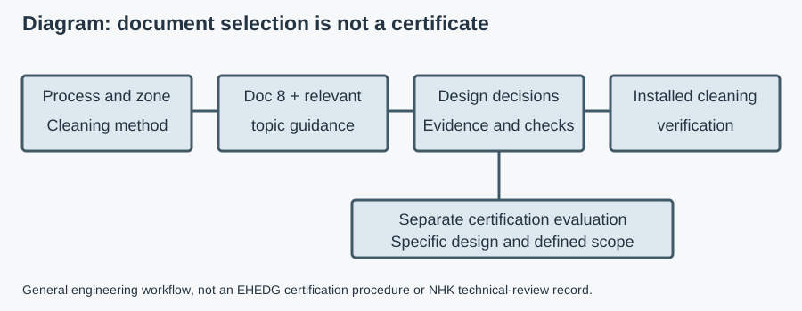
EHEDG compliant or designed to EHEDG guidelines describes a claim unless certificate evidence is provided. EHEDG certifies specific equipment designs, not materials, companies or every assembly made from certified parts. 3-A Symbol authorisation follows Third Party Verification and requires its own scope check; both schemes are voluntary.
The official EHEDG register and certificate C2300067 list NHK's 3A Spindle cover (M5–48) under EL Class I AUX. The checked revision states validity through December 31, 2026. That is a named design and listed range, not a dimension chart or proof that every accessory described as a top cover fits every foot. Request the evaluated drawing and mounting instructions for the proposed configuration.
NHK states its approved component line lists an “EHEDG-certified spindle top cover.” Match that listing to the evaluated design rather than assuming the names establish identical configurations. The product-name prefix “3A” is not independent evidence of 3-A Symbol authorisation.
NHK's published component documents are available through NHK's certifications. Request the document, evaluated design identity and mounting instructions for the proposed spindle cover. A certificate for a levelling foot does not automatically cover a different accessory or retrofit combination.
Use the supplier-claim verification workflow to compare holder, listed equipment, size/configuration, current validity and restrictions with the actual supplied item. Keep hygiene evidence separate from mechanical capacity, cleaning-chemical resistance and material/contact declarations. Stop approval when the evidence only names a broadly similar component.
Example and copyable retrofit specification
Example — hypothetical assumptions, not NHK field data. A packing conveyor has existing adjustable feet with upper thread projecting through a frame bracket. The plant proposes a sealed cover for its foam-and-rinse area. No thread size, load, cap depth, seal compound or compatibility is assumed.
The engineer documents the current height range and locking, measures the seat and upper projection, and requests a matching enclosure drawing. Maintenance checks safe removal and inspection access. QA supplies the cleaning cycle. If the cap bottoms before seating or leaves the frame cavity unresolved, the proposal is rejected until an approved compatible detail is available; the cover alone is not a machine certification.
Copy and complete: “Top/spindle cover for existing foot: __. Frame drawing and zone: __. Thread form, pitch, upper projection and seat: __. Operating height range, engagement and locking: __. Enclosure clearance and mating-surface restrictions: __. Cleaning chemicals, concentrations, temperature and contact time: __. Metal and seal evidence: __. Exact design/configuration certificate needed: __. Part numbers, quantity and delivery country: __.”
Use the buyer's component enquiry and document guides to organise those fields. Send them through the existing recommendation form below so NHK can assess available components and discuss quotation. For complete supports, the NHK stainless machine-foot line is a separate reference; it does not prove compatibility with an accessory. The NHK hygienic component category is the secondary browsing path; no universal retrofit fit, load rating or delivery promise is inferred from a category name.